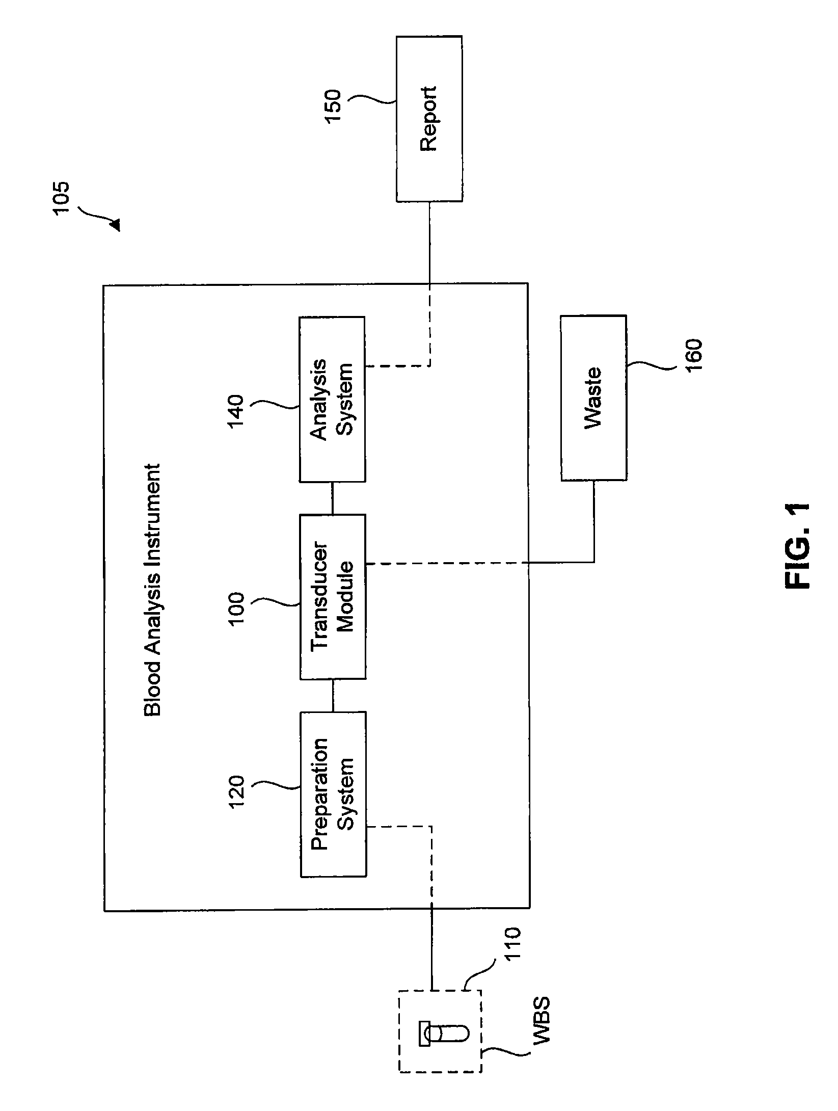
Transducer module

a transducer and module technology, applied in the field of whole blood sample analysis systems and methods, can solve the problems of relatively tight tolerances needed for optical focusing and alignment of lasers within the cell-interrogation zone, and the cost of fluorescence identification of nrbcs is relatively high,

Active Publication Date: 2012-01-10
BECKMAN COULTER INC
View PDF17 Cites 61 Cited by
  • Summary
  • Abstract
  • Description
  • Claims
  • Application Information

AI Technical Summary

Problems solved by technology

However, the use of fluorescence to identify NRBCs is relatively expensive due to the high costs of the system components and fluorescent dyes needed to stain the blood sample.
Further, in practice, the relatively tight tolerances needed for optical focusing and alignment of the laser within the cell-interrogation zone presents a significant manufacturing challenge.

Method used


Image

  • Transducer module
  • Transducer module
  • Transducer module

Examples


example 1

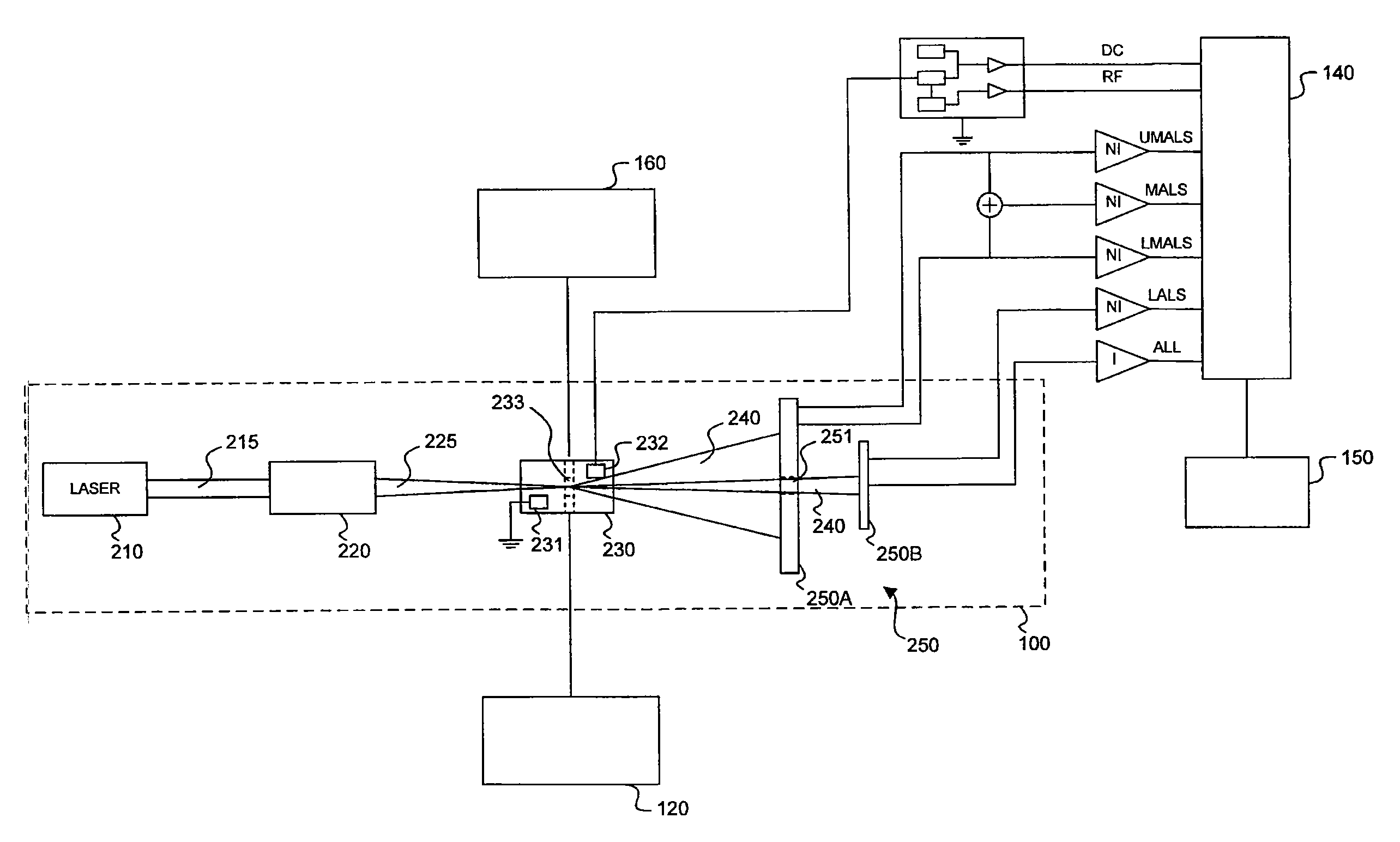
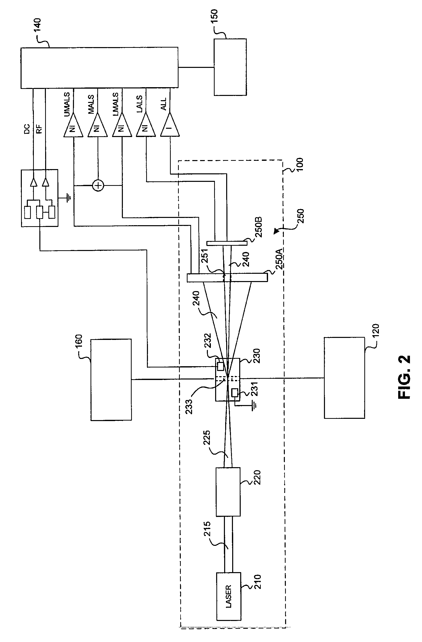
[0047]In one embodiment, there is provided a light scatter detector assembly comprising a first light scatter detector unit and a second light scatter detector unit. The first light scatter detector unit includes a first photoactive region for detecting UMALS, a second photoactive region for detecting LMALS, and an opening provided to allow low angle light scatter to pass beyond the first light scatter detector unit. The second light scatter detector unit is posterior to the first light scatter detector unit, and includes an axial light loss sensor. The second light scatter detector unit further includes one or more LALS sensors disposed proximate to the axial light loss sensor.

example 2

[0048]In one embodiment, there is provided a laser light focus-alignment system for use in a transducer module, comprising a first adjustment means for lateral alignment of a laser beam and a second adjustment means for longitudinal alignment of the laser beam. The second adjustment means is mounted on a movable carrier such that movement of the carrier axially positions a focal point of the laser beam. In one embodiment, the first adjustment means includes a first lens, wherein positional movement of the first lens aligns the laser beam in a x-direction, the second adjustment means includes a second lens, wherein positional movement of the second lens aligns the laser beam in a y-direction, and the movement of the movable carrier positions the focal point of the laser beam in a z-direction, wherein the x-direction, y-direction, and z-direction are relative to a laser light source. In alternative embodiments, the first adjustment means includes a flexure hinge and the second adjustm...

example 3

[0049]In one embodiment, there is provide a transducer module comprising a fixed laser light source, a first lens proximate to the laser light source for lateral alignment of a laser beam emitted by the laser light source, a second lens mounted on a movable carrier, wherein the second lens provides longitudinal alignment of the laser beam, and wherein movement of the carrier axially positions a focal point of the laser beam, and a fixed flow cell.


PUM

PropertyMeasurementUnit
anglesaaaaaaaaaa
anglesaaaaaaaaaa
lengthaaaaaaaaaa

Abstract

Transducer modules for use in a blood analysis instrument and methods for analyzing a blood sample. The transducer modules presented generally include a light source, a focus-alignment system, a flow cell, and a light scatter detection system. Electrodes within the flow cell allow for the measurement of the DC impedance and RF conductivity of cells passing through a cell-interrogation zone in the flow cell. Light scatter from the cells passing through the cell-interrogation zone is measured by the light scatter detection system. The light scatter detection system measures the light scatter parameters of upper median light scatter, lower median angle light scatter, low angle light scatter, and axial light loss. The presented methods for analyzing a blood sample generally include aspirating a whole blood sample into a blood analysis instrument, preparing the blood sample for analysis, passing the blood sample through a flow cell in a transducer system, and measuring axial light loss, multiple angles of light scatter, DC impedance and / or RF conductivity.

Description

BACKGROUND OF THE INVENTION[0001]1. Field of the Invention[0002]The present invention relates to systems and methods for analyzing a whole blood sample. More specifically, the present invention relates to a transducer module for use in a blood analysis instrument.[0003]2. Background Art[0004]In diagnosing different illnesses and disease states, it is common to analyze a patient's peripheral blood to differentiate and enumerate the various constituents within the blood, as well as to determine certain parameters or characteristics of those constituents. For example, a whole blood sample (WBS) generally comprises various types of cells (both blood cells and non-blood cells) suspended in a liquid medium or plasma. The blood cells are three basic types, namely, red cells (erythrocytes), white cells (leukocytes), and platelets (thrombocytes). Depending on the level of maturity, red cells are often further classified into three subsets, namely, nucleated red blood cells (NRBCs), reticulat...

Claims


Application Information

Patent Timeline
Patent Type & Authority Patents(United States)
IPC IPC(8): G01N21/01
CPCG01N15/147G01N21/532G01N2015/0073G01N2015/1037G01N2015/008G01N2015/0084G01N2015/0076G01N15/1459
Inventor WELLS, MARK A.PEREZ, CARLOS A.CANO, JOSE M.
Owner BECKMAN COULTER INC
Why Eureka
Try Eureka