Bridgeless power factor correction circuit

a power factor and circuit technology, applied in the direction of electric variable regulation, process and machine control, instruments, etc., can solve the problems of difficult voltage stabilization, complex configuration circuits, and increased size and volume, and achieve the effect of removing common mode noise of input power

Active Publication Date: 2012-01-10
SOLUM CO LTD
View PDF5 Cites 13 Cited by
  • Summary
  • Abstract
  • Description
  • Claims
  • Application Information

AI Technical Summary

Benefits of technology

[0024]The switching unit may further include first and second diodes removing common mode noise of the input power.

Problems solved by technology

However, it is difficult to stabilize a voltage since the size of an output voltage varies according to the size of an input power voltage.
Further, since the passive power factor correction circuit needs to be designed according to commercial power frequency, it increases in size and volume significantly.
However, since the active power factor correction circuit uses a switching method, a configuration circuit becomes complex to increase the unit cost, and it becomes difficult to control the circuit.
The bridge diodes BD cause high conduction loss of approximately 2 to 3% of all power capacity.

Method used


Image

  • Bridgeless power factor correction circuit
  • Bridgeless power factor correction circuit
  • Bridgeless power factor correction circuit

Examples


Embodiment Construction

[0040]Exemplary embodiments of the present invention will now be described in detail with reference to the accompanying drawings.

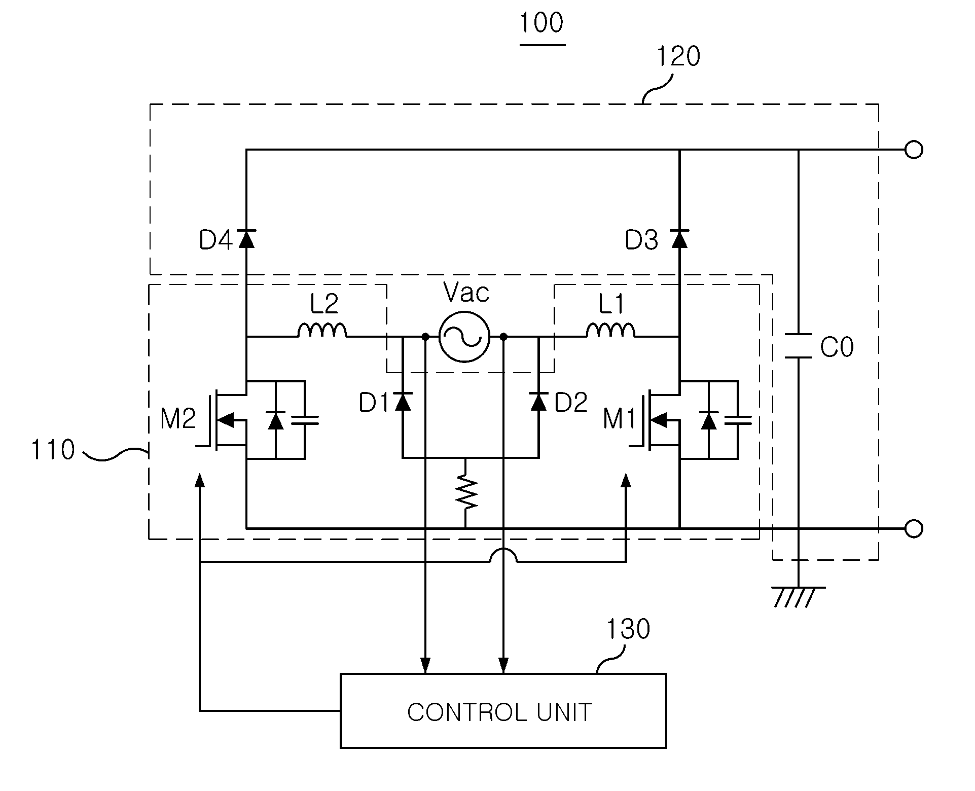
[0041]FIG. 4 is a circuit diagram illustrating a bridgeless power factor circuit according to an exemplary embodiment of the present invention.

[0042]Referring to FIG. 4, a bridgeless power factor correction circuit 100 according to an exemplary embodiment of the invention includes a switching unit 110, a stabilizing unit 120, and a control unit 130.

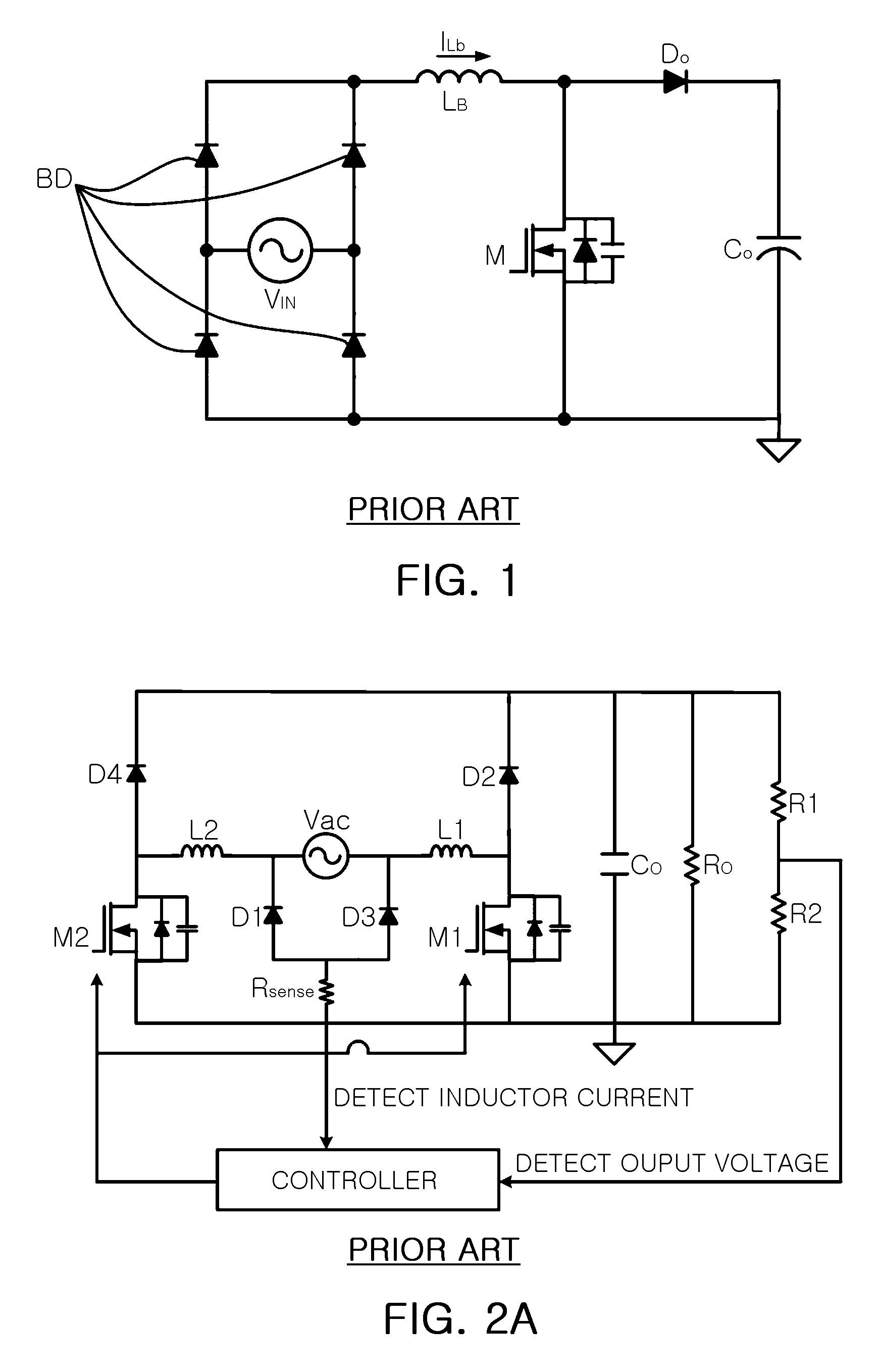
[0043]The switching unit 110 includes first and second inductors L1 and L2 that are individually connected in series with an input AC power Vac terminal, and first and second switches M1 and M2 that are connected to the first and second inductors L1 and L2, respectively.

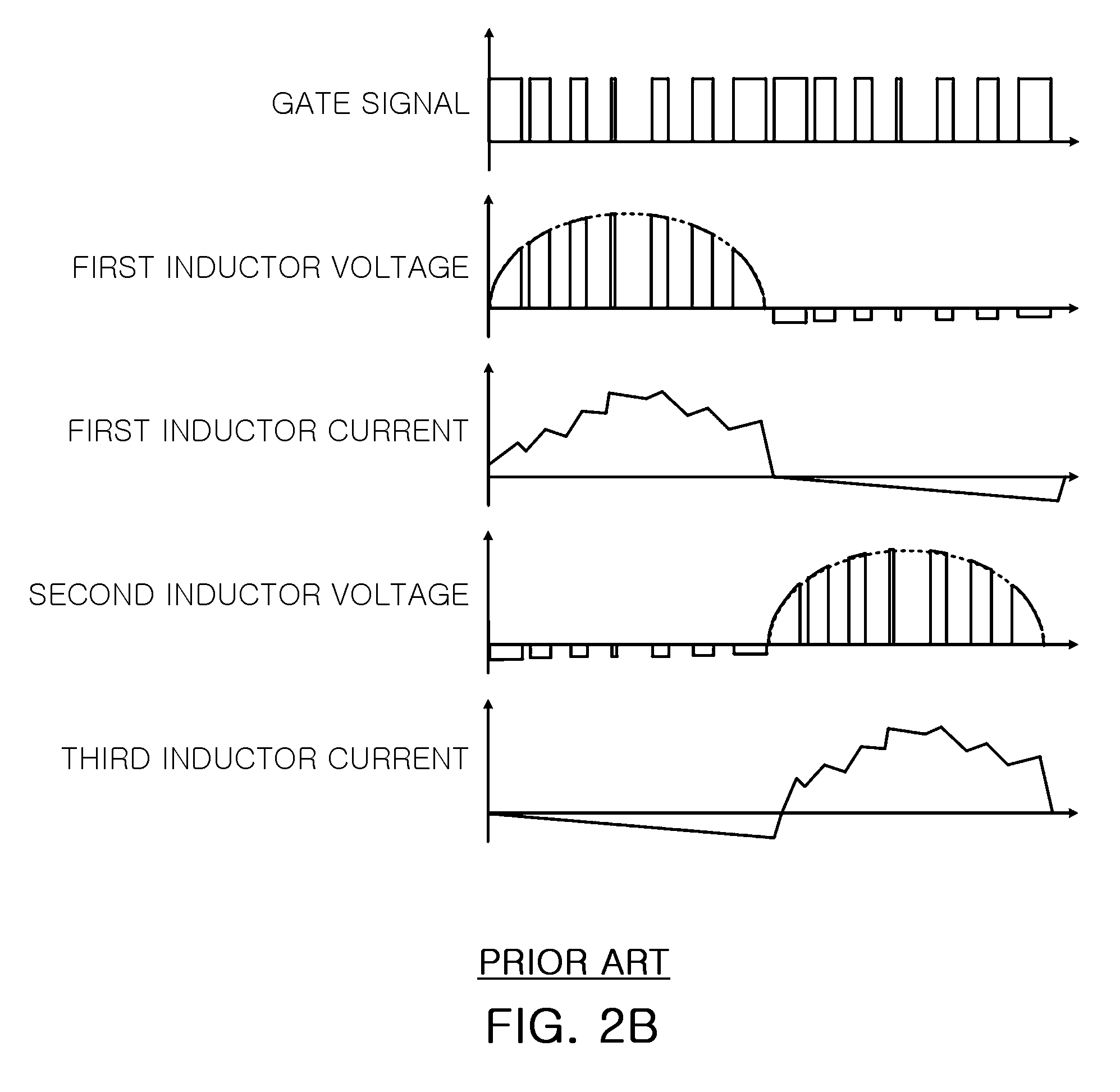
[0044]The first and second inductors L1 and L2 are used as boost inductors according to a switching operation between the first and second switches M1 and M2. The first and second switches M1 and M2 are alternately turned on and off according to ...


PUM


Abstract

There is provided a bridgeless power factor correction circuit that corrects a power factor by complementarily switching two switches according to phase of input power without using rectifier bridge diodes. A bridgeless power factor correction circuit according to an aspect of the invention may include: a switching unit having a plurality of switches and alternately switching input AC power; a stabilizing unit rectifying and smoothing the power switched by the switching unit; and a control unit controlling an alternate switching operation between the plurality of switches according to phases of the input power.

Description

CROSS-REFERENCE TO RELATED APPLICATIONS[0001]This application claims the priority of Korean Patent Application No. 2007-0140713 filed on Dec. 28, 2007, in the Korean Intellectual Property Office, the disclosure of which is incorporated herein by reference.BACKGROUND OF THE INVENTION[0002]1. Field of the Invention[0003]The present invention relates to a bridgeless power factor correction circuit, and more particularly, to a bridgeless power factor correction circuit that corrects a power factor by complementarily switching two switches on and off according to phases of input power without using a rectifier bridge diode.[0004]2. Description of the Related Art[0005]In recent years, as harmonics regulations have been tightened worldwide, the use of power factor correction circuits in electronic products has become common and required.[0006]In general, the power factor correction circuit is divided into a passive power factor correction circuit and an active power factor circuit. The pas...

Claims


Application Information

Patent Timeline
Patent Type & Authority Patents(United States)
IPC IPC(8): H02M7/04
CPCH02M1/4225Y02B70/126Y02B70/10Y02P80/10G05F3/06
Inventor MOON, GUN WOOLEE, DONG WOOKCHO, KYU MINCHOI, SEONG WOOKKIM, DON SIKKIM, JONG PILBONG, SANG CHEOLKIM, DONG JOONGHEO, TAE WON
Owner SOLUM CO LTD
Why Eureka
Try Eureka