Micro acoustic transducer and manufacturing method therefor

a micro-acoustic transducer and manufacturing method technology, applied in the field of acoustic structure, can solve the problems of significant impact of residual stress, and achieve the effect of enhancing firmness and enhancing mechanical sensitivity of thin films

Active Publication Date: 2012-01-10
IND TECH RES INST
View PDF10 Cites 8 Cited by
  • Summary
  • Abstract
  • Description
  • Claims
  • Application Information

AI Technical Summary

Benefits of technology

[0010]An object of the invention is to provide a micro acoustic transducer to overcome the technology problems in prior art. A structure of rings is used as a boundary condition to enhance the mechanical sensitivity of a thin film. Besides, a substrate of a single crystal support structure is formed on the backplate structure to support the backplate, thereby enhancing firmness and solving the problems existing in the prior art.
[0011]An object of the invention is to provide a method of manufacturing micro acoustic transducer to overcome another technology problems in prior art. In order to enhance the stability of the structure of the backplate, the invention provides a method to define acoustic hole regions with sacrificial layers, such that the substrate is etched into a single crystal support structure to support the backplate.
[0018]The micro acoustic transducer provided by the invention is directed to enhancing the sensitivity of the micro acoustic transducer. When the acoustic wave is transmitted, the capacitance value changes due to the structural distortion of diaphragm caused by the change of sound pressure, so as to read the signal of the acoustic wave. As for the design of the structure, a diaphragm structure with high sensitivity and a backplate structure that is kept to be a plane are desired to form a capacitor structure with a thin film structure.
[0021]On the other hand, in order to achieve the design of the backplate structure that is kept to be a plane, in many conventional arts, the stiffness of the backplate structure is enhanced through folding of the structure, doped silicon used as an etch stop layer, or a single crystal structure of silicon used as the backplate structure. In the invention, after the substrate is etched to a certain depth by backside etching, the sacrificial layer and the substrate are etched on the front side through etch holes to form a backplate support structure with acoustic holes, because the backplate structure supported by the single crystal structure helps to strengthen the stability of the backplate structure.

Problems solved by technology

However, according to the result of theoretical modeling, residual stress plays a significant impact on the mechanical sensitivity of a diaphragm in an acoustic transducer.
Under the influence of the residual stress, the boundary conditions of the diaphragm must be changed or a folding structure must be formed, so as to enhance the mechanical sensitivity of the diaphragm; therefore, how to provide a structure and method for a diaphragm to achieve a better stress-releasing effect and improve the property of a microphone component become an important issue.

Method used


Image

  • Micro acoustic transducer and manufacturing method therefor
  • Micro acoustic transducer and manufacturing method therefor
  • Micro acoustic transducer and manufacturing method therefor

Examples


first embodiment

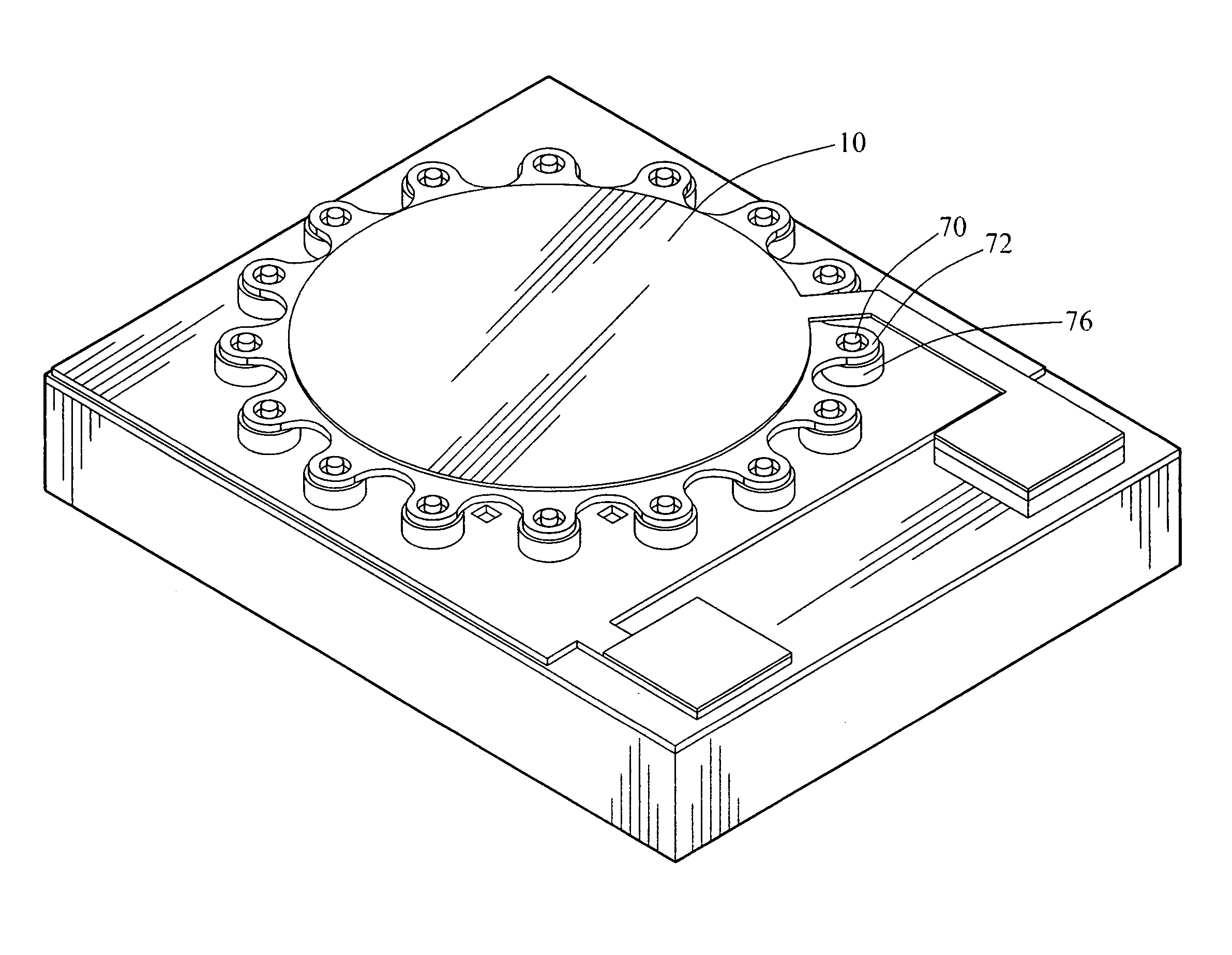
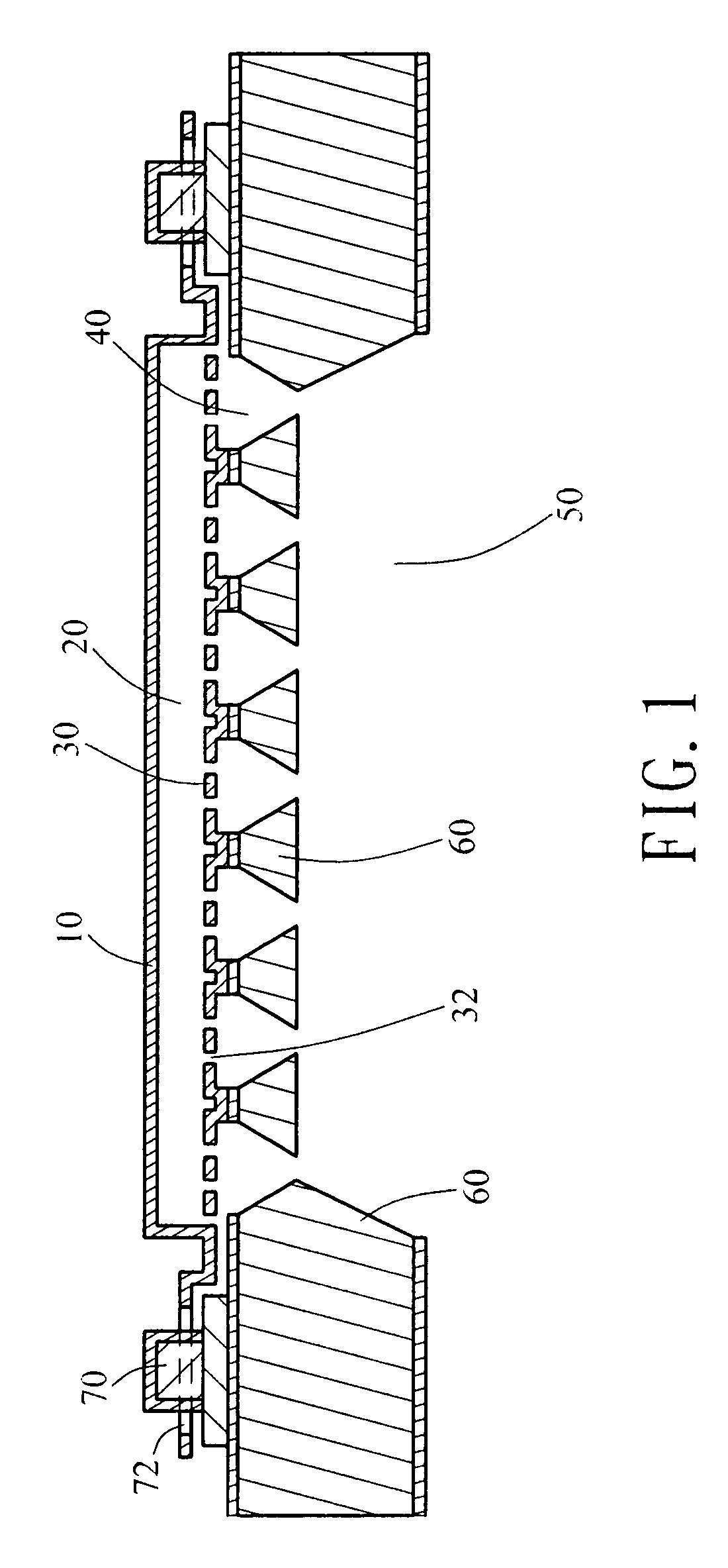
[0036]Referring to FIG. 1, it is a schematic structural view of the micro acoustic transducer of the invention. The micro acoustic transducer comprises a substrate 60 such as a silicon substrate, a backplate 30 formed on the substrate 60, a diaphragm 10 formed above the backplate 30, and a plurality of pillars 70 formed on the substrate 60 and around the diaphragm 10. The shape of the diaphragm 10 is square, circular, finger-like, or any other shape. A plurality of rings 72 is formed around the diaphragm 10 to hitch the pillars. Each ring 72 hitches one corresponding pillar 70, but does not completely fix the pillar. The diameter of the hole of each ring is larger that that of each pillar, such that the diaphragm 10 is still a free thin film. The pillars 70 are only used to limit the moving range of the diaphragm 10 on the plane. Further, an air gap 20 is formed between the diaphragm 10 and the backplate 30 with multiple acoustic holes 32. A first cavity 50 and a second cavity 40 ar...

second embodiment

[0041]As shown in FIG. 7, it is a top view of the micro acoustic transducer of the invention, FIG. 8 is a schematic sectional view of FIG. 7, and FIG. 9 is a stereogram view of FIG. 7. The micro acoustic transducer comprises a substrate 60a with at least one first cavity 50a and one second cavity 40a communicated with the first cavity 50a, a backplate 30a formed on the substrate 60a with multiple acoustic holes 32a, a diaphragm 10a formed on the backplate 30a with a plurality of fastener holes 80 around the diaphragm 10a, a plurality of fastener 81 formed on the substrate 60a and the position of each fastener 81 is corresponding to that of each fastener hole respectively, and a plurality of supporting element formed on the diaphragm 10a. The supporting element 82 includes a supporting rod 821 formed on the diaphragm 10a, a supporting pin 822 is vertically extended from the supporting rod 821, and a fixed end 823 is horizontally extended from the supporting rod 821. The supporting el...


PUM


Abstract

A micro acoustic transducer and manufacturing method are provided. Firstly, a substrate having one first and second cavities is provided. Then, a backplate with a plurality of acoustic holes is formed on the substrate, and a diaphragm is formed on the backplate. An air gap is formed between the backplate and the diaphragm. The air gap, second cavity, and first cavity are communicated with each other through the acoustic holes. A plurality of rings is formed around the diaphragm. These rings are used to hitch pillars formed on the substrate or fasteners can be formed on the substrate for fastening the diaphragm on fastener holes. Through the arrangement of the rings or fasteners used as the boundary structure of the diaphragm, the mechanical sensitivity of the diaphragm is improved. Moreover, the backplate is supported by a single crystal structure formed by etching the substrate such that the stability is promoted.

Description

CROSS-REFERENCE TO RELATED APPLICATIONS[0001]This non-provisional application claims priorities under 35 U.S.C. §119(a) on Patent Application No(s). 095100667 and 095138475 filed in Taiwan, R.O.C. on Jan. 6, 2006 and Oct. 18, 2006, the entire contents of which are hereby incorporated by reference.BACKGROUND OF THE INVENTION[0002]1. Field of Invention[0003]The invention relates to an acoustic structure, and more particularly, to a micro acoustic transducer and a manufacturing method therefor.[0004]2. Related Art[0005]Micro acoustic transducers developed are mainly applied in various acoustic receivers and it has become an object of the design thereof to pursue characteristics such as small volume, low power consumption, and high sensitivity. Further, according to the result of theoretical modeling, it can be known that residual stress has a significant impact on the mechanical sensitivity of a diaphragm in an acoustic transducer. Under the influence of the residual stress, the bounda...

Claims


Application Information

Patent Timeline
Patent Type & Authority Patents(United States)
IPC IPC(8): H04R25/00
CPCH04R19/00
Inventor SUNG, PO-HSUN
Owner IND TECH RES INST
Why Eureka
Try Eureka