Evacuable magnetron chamber

a magnetron chamber and vacuum pumping technology, applied in the field of sputtering of materials, can solve the problems of unpractical configuration, large sputtering reactors, and conventional pumping systems, and achieve the effects of improving the efficiency of the sputtering chamber and the sputtering chamber

Inactive Publication Date: 2012-01-17
APPLIED MATERIALS INC
View PDF6 Cites 1 Cited by
  • Summary
  • Abstract
  • Description
  • Claims
  • Application Information

AI Technical Summary

Problems solved by technology

This large size has introduced several problems not experienced in wafer fabrication equipment limited to sizes of about 300mm in the most recent equipment.
However, such a configuration is unpractical with sputter reactors for large panels.
The conventional pumping system, however, suffers several drawbacks.
Large pressure differentials may cause the backing plate 20 to permanently deform and even fracture.
Large sputtering targets, particularly of refractory materials such as molybdenum, are exceedingly expensive and target failures due to pumping accidents need to be minimized.

Method used


Image

  • Evacuable magnetron chamber
  • Evacuable magnetron chamber
  • Evacuable magnetron chamber

Examples


Embodiment Construction

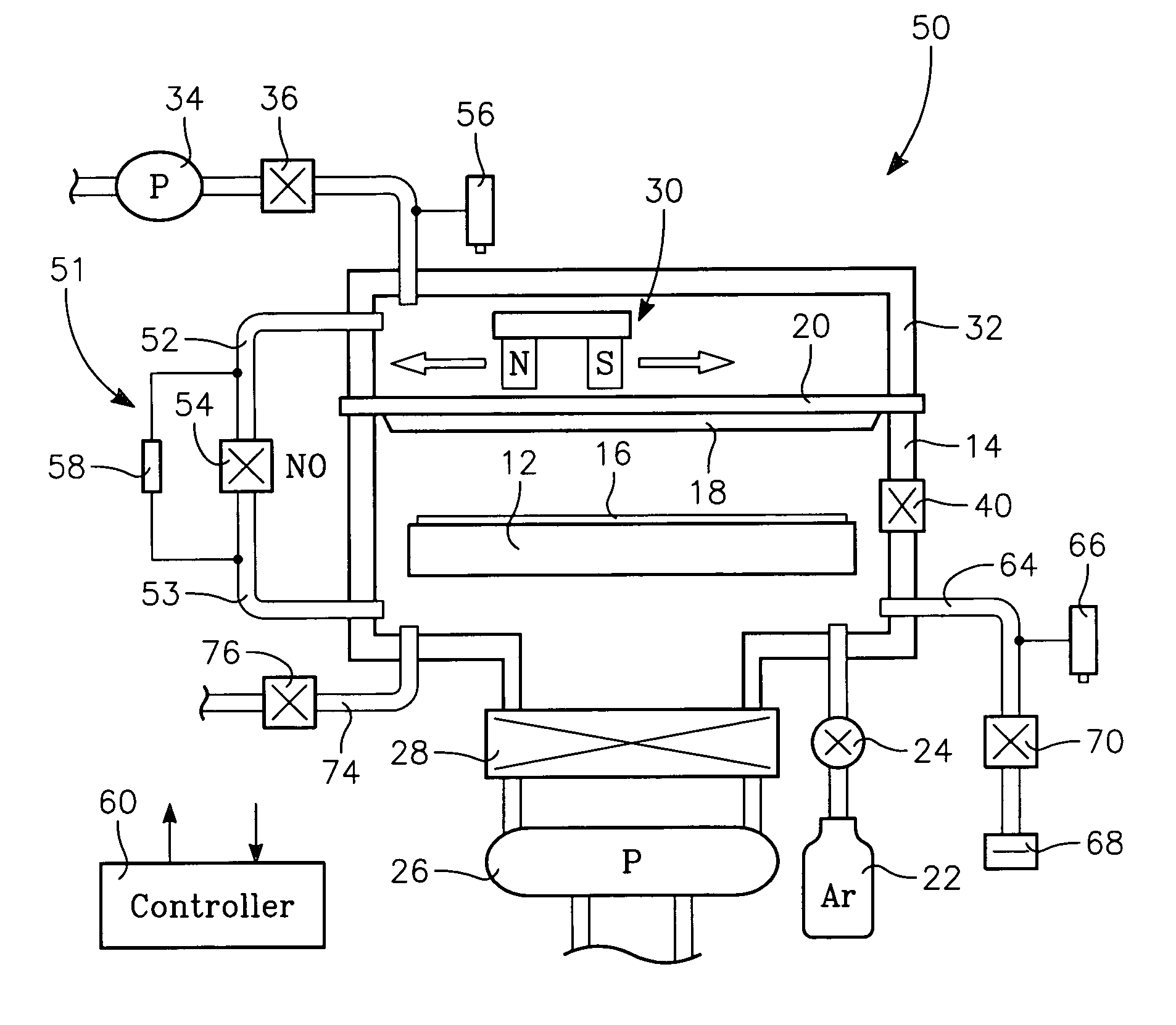
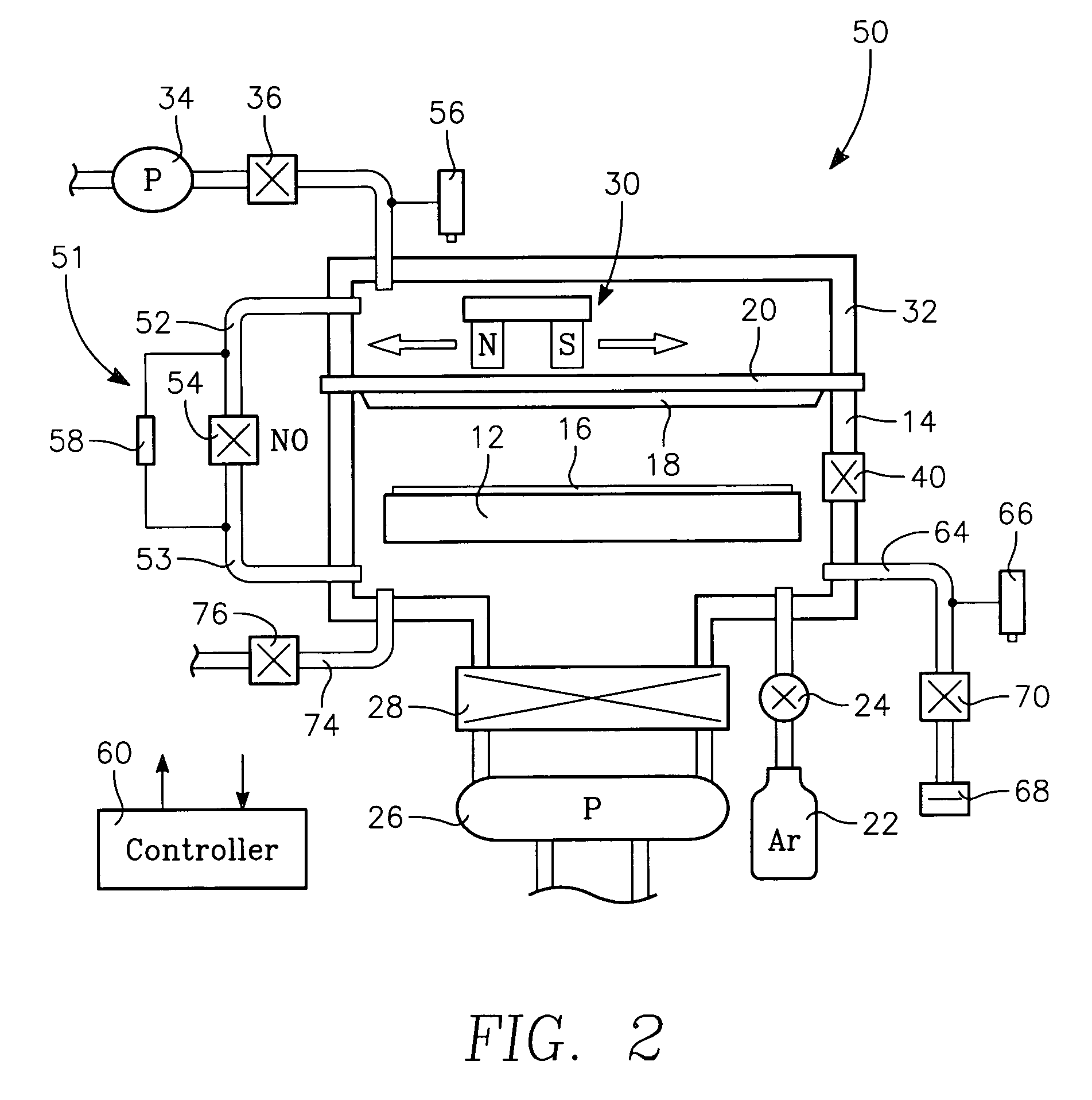
[0014]An inventive sputter reactor 50, schematically illustrated in the cross-sectional view of FIG. 2, differs from the conventional reactor mostly in its gas pumping and pressure monitoring. The mechanical roughing pump 34 is connected to the magnetron chamber 32 through the roughing valve 36 to rough pump both the magnetron chamber 32 and the main chamber 14. A bypass conduit 51 includes a magnetron gas line 52 connected to the magnetron chamber 32 and a main chamber gas line 53 connected to the processing chamber 14 and an intermediate bypass gate valve 54. Whether the bypass gate valve 54 is open or closed determines whether the two chambers 14, 32 are vacuum isolated from each other or pressure equalized. In this embodiment, it is preferred that there be no other valving on the bypass conduit 51. With this configuration, there is no need for a direct connection from the roughing pump 34 to the main chamber 14 since the roughing pump 34 can pump the processing chamber 14 throug...


PUM

PropertyMeasurementUnit
sizesaaaaaaaaaa
sizesaaaaaaaaaa
sizesaaaaaaaaaa

Abstract

A vacuum pumping system and method in conjunction with a sputter reactor having a vacuum-pumped magnetron chamber sealed to the target backing plate. A main sputter chamber is vacuum sealed to the target front and cryo pumped. A bypass conduit and valve connect the magnetron and main chambers. A mechanical roughing pump connected to the magnetron chamber pumps the main chamber through the bypass conduit to less than 1 Torr before the bypass valve is closed and the cryo pump is opened and thereafter continues to pump the magnetron chamber to reduce the pressure differential across the target. A pressure differential switch connected across the bypass valve immediately open it whenever the pressure differential exceeds a limit, such as 20 Torr, for example when there is a leak or an electrical failure. The bypass conduit is also used in a venting procedure.

Description

FIELD OF THE INVENTION[0001]The invention relates generally to sputtering of materials. In particular, the invention relates to the vacuum pumping system of the sputtering chamber.BACKGROUND ART[0002]Sputtering is a well established technology in the fabrication of silicon integrated circuits in which a metal target is sputtered to deposit target material onto the silicon wafer. In recent years, sputtering has also been applied for similar purposes in the fabrication of flat panel displays, such as flat computer displays and large flat televisions and the like. Various types of flat panel displays may be fabricated typically including thin film transistors (TFTs) formed on large thin insulating rectangular substrates, often called panels, such as glass or polymer and including liquid crystal displays (LCDs), plasma displays, field emitters, and organic light emitting diodes (OLEDs). Almost all panel fabrication equipment is distinguished by its large size. The original generation wa...

Claims


Application Information

Patent Timeline
Patent Type & Authority Patents(United States)
IPC IPC(8): C23C14/54
CPCC23C14/35C23C14/56H01J37/32449H01J37/3408
Inventor INAGAWA, MAKOTO
Owner APPLIED MATERIALS INC
Why Eureka
Try Eureka