Ram air driven turbine generator battery charging system using control of turbine generator torque to extend the range of an electric vehicle

a technology of turbine generator and turbine torque, which is applied in the direction of electric generator control, electrochemical generators, secondary cells servicing/maintenance, etc., can solve the problems of increasing the torque load of the turbine, increasing the electrical load of the generator, and increasing the drag resistance of the turbine, so as to maximize the harvest of ram air kinetic energy, enhance the management of the turbine torque and the generator output, and minimize the effect of the increase of the turbine caused drag

Inactive Publication Date: 2012-01-17
BOTTO DAVID CHANDLER
View PDF37 Cites 53 Cited by
  • Summary
  • Abstract
  • Description
  • Claims
  • Application Information

AI Technical Summary

Benefits of technology

[0007]The present embodiment provides for a ram air powered battery charging system, including ultra capacitor assist, that will extend significantly the driving range of an electrically powered vehicle beyond that otherwise achieved before external charging is required. The embodiment maintains the desired charging current to the battery while minimizing the ram air turbine caused drag resistance of the vehicle at most vehicle speeds and levels of battery charge.
[0009]This embodiment includes the means to vary the angular position, or pitch, of the turbine blades relative to the direction of ram air flow to ensure maximum harvest of ram air kinetic energy at low speeds while controlling turbine speed, generator output and turbine caused drag resistance at highway speeds. A further embodiment includes programmed control of a variable air gap between stator and rotor of the generator, as in prior art, to enhance management of turbine torque and generator output. This embodiment also includes a programmed charging profile, obtained through ultra capacitor technology, to maintain a pre-determined level of electrical load at the generator outputs as the battery approaches full charge. By efficiently maintaining an optimum electrical load on the turbine generator, the opposing torque load on the turbine is kept at a level that allows efficient battery charging to continue at an appropriate rate with minimal increase in turbine caused drag. The ultra capacitor also provides short term power boost to the traction drive motor for vehicle acceleration. These capabilities together provide sufficient management of battery charging performance and turbine caused drag to extend vehicle driving range.
[0010]The main advantage of the embodiment is that it will enable continuous ram air driven battery charging of an electric vehicle during most vehicle speeds and levels of battery charge while maintaining acceptable levels of turbine caused drag, thereby efficiently converting the kinetic energy of ram air flow, developed by a powered vehicle in motion, to generate and store electrical energy. The present embodiment will extend the driving range of an electrically powered vehicle between times that battery charging by external means is required.
[0011]Another advantage of this embodiment is that it will provide capacitor stored energy for surge power during acceleration.
[0012]Another advantage of this embodiment is that it will fit many configurations of modern vehicles with little change to basic body and frame design.
[0013]Another advantage of this embodiment is that it enables reduction of turbine noise at highway speeds.

Problems solved by technology

The many embodiments in prior art do not consider adequately the fundamental issues inherent in converting and storing the ram air kinetic energy developed by a vehicle in motion, that is, (a) the ram air energy necessary to cause the turbine generator to rotate manifests as additional vehicle drag which, if vehicle speed is to be maintained, must be overcome by the application of additional traction drive energy and; (b) as the vehicle battery approaches full charge, the increased electrical load on the generator increases which increases the torque load on the turbine, adding to the turbine caused drag resistance.
Prior art devices to control battery charge resistance affect on generator load are effective but slow acting and not efficient.
The two effects are limiting in any attempt to achieve a functionally useable result in converting and storing the ram air energy of a moving electric vehicle that, in normal use, operates in a wide range of speeds and battery charge levels.

Method used


Image

  • Ram air driven turbine generator battery charging system using control of turbine generator torque to extend the range of an electric vehicle
  • Ram air driven turbine generator battery charging system using control of turbine generator torque to extend the range of an electric vehicle
  • Ram air driven turbine generator battery charging system using control of turbine generator torque to extend the range of an electric vehicle

Examples


Embodiment Construction

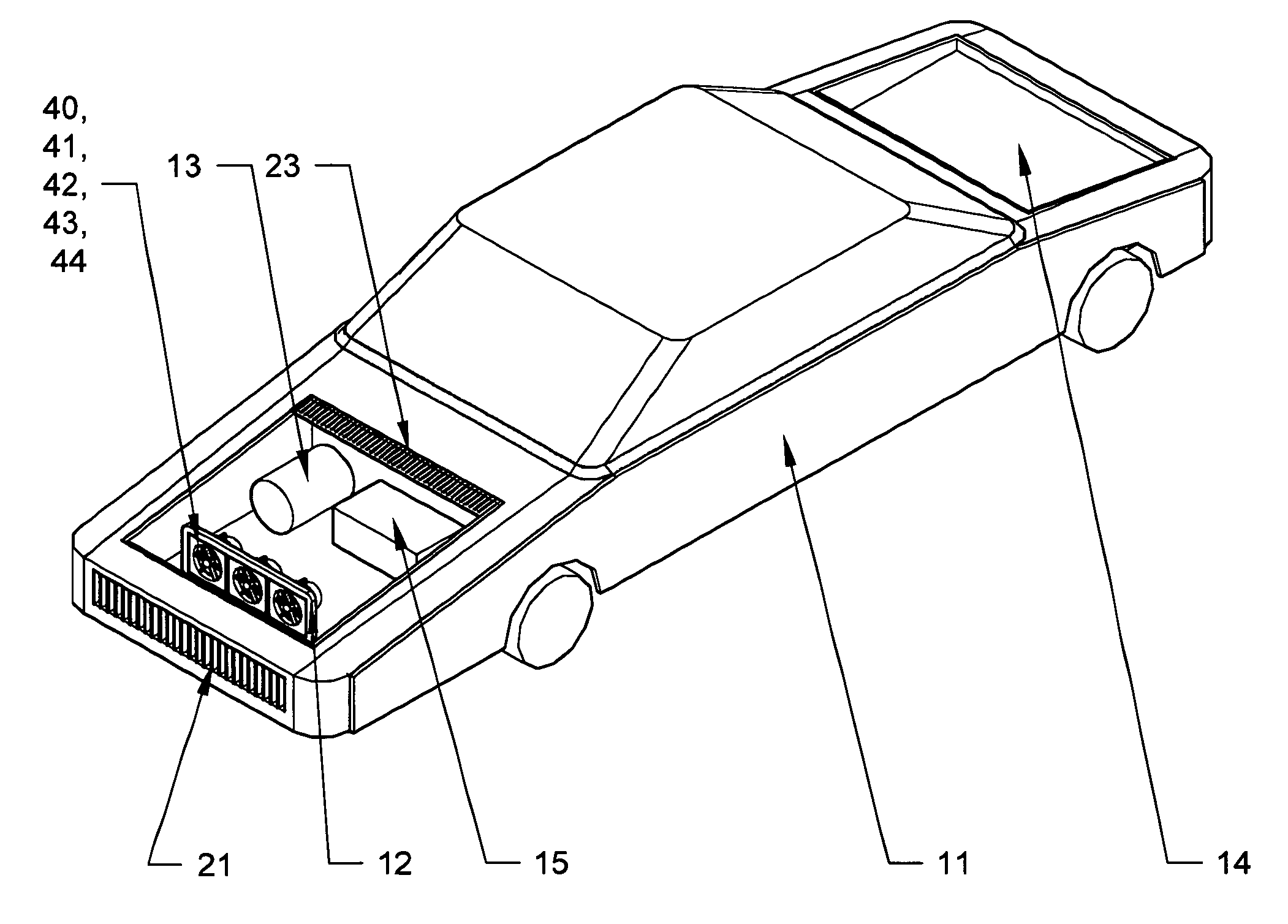
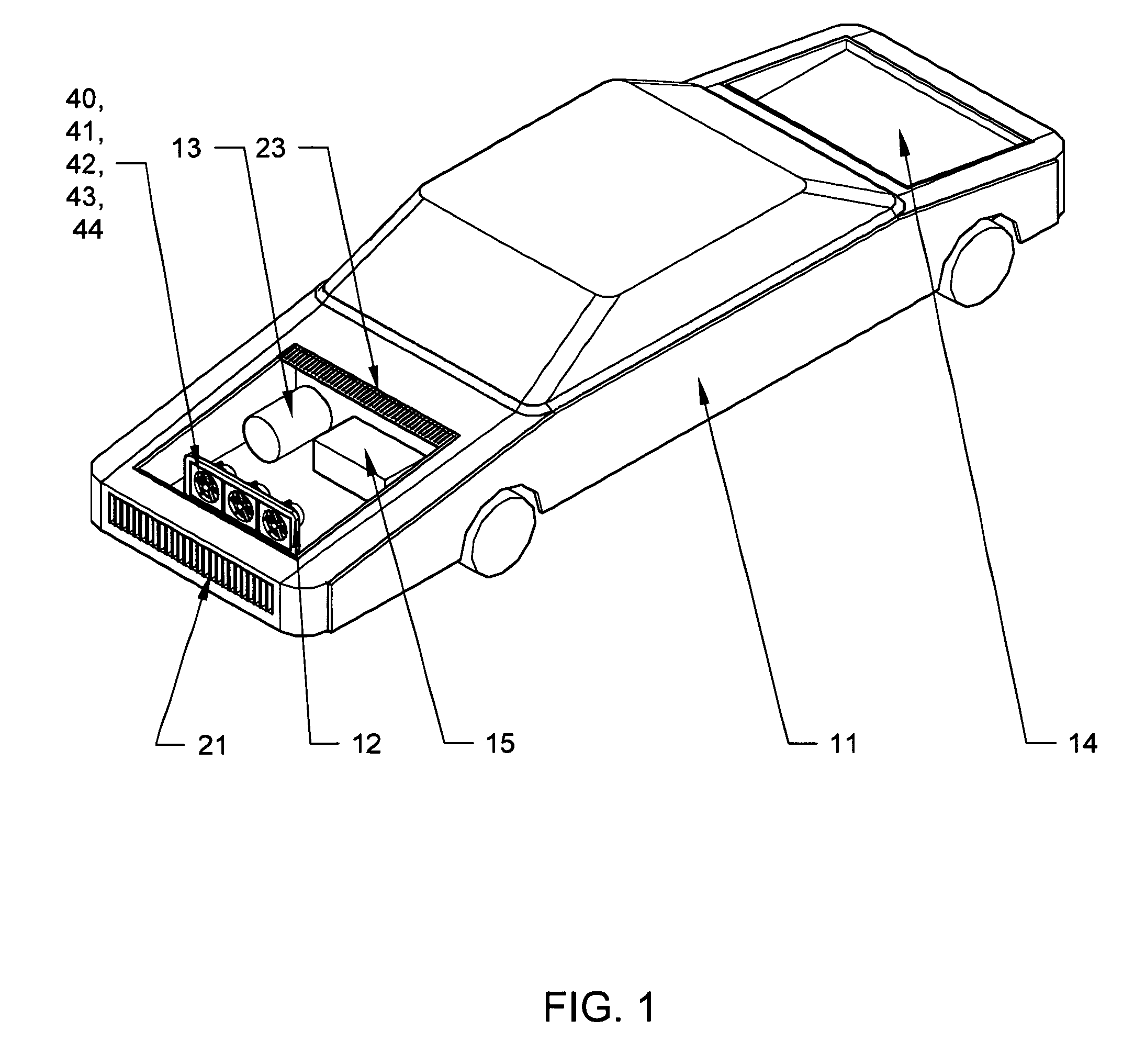
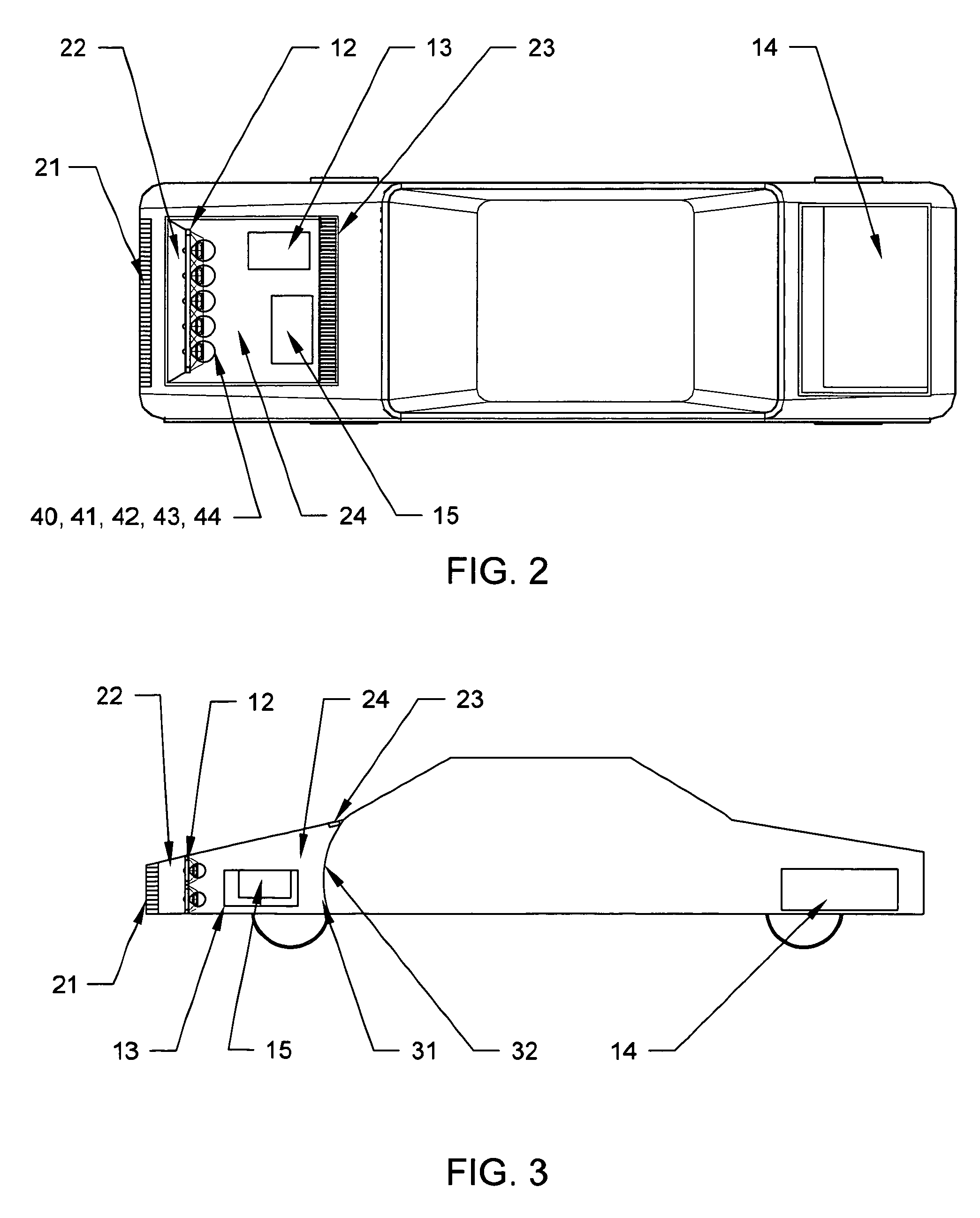
[0052]FIG. 1 shows the major electrical components of the embodiment as typically installed in an electrically powered vehicle 11. Turbine generator mounting assembly 12, containing turbine generators 40, 41, 42, 43, 44, is fixed in a forward position in the front compartment of the vehicle, mounted to the frame and body of the vehicle. Electric traction drive motor 13 will be typically mounted in the front compartment. Vehicle battery 14 is shown for illustration in the rear of the vehicle and may be a multiple cell battery or a set of such batteries comprising a battery pack. One battery or pack is shown in this embodiment but in an alternative embodiment two separate and equivalent batteries are used with one an active drive energy source and the other a ‘hot’ spare being charged by the ram air charging system. When the active battery reaches a pre-programmed minimum level of charge, the batteries are electrically switched and their roles reversed thereby further extending the ve...


PUM

PropertyMeasurementUnit
charge resistanceaaaaaaaaaa
speedaaaaaaaaaa
electrical resistanceaaaaaaaaaa

Abstract

A system and method to convert the ram air energy resulting from the movement of an electric vehicle through the air mass into electric energy to recharge the energy storage devices of the vehicle while minimizing the apparatus caused drag effect on the vehicle, thereby extending the driving range of the vehicle between external charging. At least one ram air driven turbine is positioned within the vehicle, the turbine driving a mechanically coupled generator to charge the battery. Ram air is ducted in the front of the vehicle to cause the turbine generator to rotate and output electrical energy to charge the battery. The effect of variation in vehicle speed on both turbine generator output and turbine caused drag is optimized by adjusting the pitch angle of the turbine blades. At least one included ultra capacitor will implement a pre-programmed charge / discharge profile to reduce charge resistance electrical loading on the turbine generator and enable continued battery charging with minimal increase of turbine caused drag.

Description

CROSS REFERENCE TO RELATED APPLICATIONS[0001]This application claims the benefit of PPA Ser. No. 61 / 132,997, filed 2008 Jun. 25 by the present inventor.STATEMENT REGARDING FEDERALLY SPONSORED RESEARCH OR DEVELOPMENT[0002]Not ApplicableREFERENCE TO SEQUENCING LISTING, A TABLE, OR A COMPUTER PROGRAM LISTING COMPACT DISC APPENDIX[0003]Not applicableBACKGROUND OF THE INVENTION[0004]The present invention relates to an electrically powered motor vehicle and, specifically, to a ram air driven turbine generator charging system for the vehicle that utilizes control of both turbine torque and electrical loading at the generator output to charge the vehicle battery and power the vehicle while minimizing the turbine caused drag resistance of the vehicle.[0005]Prior art describes wind powered electric generator systems mounted on the roof, the hood or internal to an electric vehicle to charge the vehicle battery while the vehicle is in motion (Guenard, 2002 / 0066608, 2002; Deets, U.S. Pat. No. 7,...

Claims


Application Information

Patent Timeline
Patent Type & Authority Patents(United States)
IPC IPC(8): H01M10/44
CPCB60L8/006Y02T10/7083Y02T10/7072
Inventor BOTTO, DAVID CHANDLER
Owner BOTTO DAVID CHANDLER
Why Eureka
Try Eureka