
Procedure for the loading of a working cylinder, control module for it, working cylinder and utilization of the same

a technology for working cylinders and control modules, applied in metal-working holders, positioning devices, supports, etc., can solve the problems of reducing the efficiency of working cylinders, and reducing the cost of operation, so as to save costs and improve energy balan

Active Publication Date: 2012-01-24
TUNKERS MASCHENBAU
View PDF12 Cites 7 Cited by
  • Summary
  • Abstract
  • Description
  • Claims
  • Application Information

AI Technical Summary

Benefits of technology

[0008]The invention is based on the problem of doing away with the disadvantages of the state of the art and helping to considerably improve the energy balance and save costs in all areas, that means, both in the case of the procedures known so far for the loading of working cylinders, primarily for use in the manufacture of motor vehicle bodywork and in the case of the control module for fluid under pressure for loading working cylinders of this kind and in the case of the use of working cylinders for devices for tensioning, compressing, joining, stamping, embossing, punching and welding.
[0010]In order to adjust the different pressures during the idle stroke and power stroke in keeping with the output, particularly the air flow or hydraulic fluid flow rate, in the case of the procedure according to the invention one working cylinder is filled with pressure medium on both sides of the piston during the idle stroke so that during the idle stroke (setting stroke) only the differential pressure, which is the difference between the piston surface loaded by the fluid pressure and the opposite side of the piston-ring surface, acts in the direction of the working stroke. The fluid and in particular energy consumption for the pump and its drive motor, particularly compressed air and hydraulic fluid consumption, are considerably reduced, for example, by 50%, by it.
[0016]Working cylinders designed in accordance with the invention can be used to great advantage in many forms, particularly in the automotive industry, for example, in devices for tensioning, compressing, jointing, stamping, embossing, punching and welding in the manufacture of motor vehicle bodywork. Existing production lines can be fitted with working cylinders of the kind forming the object of the invention without structural changes, thus enabling the cost of energy for operating production lines of this kind to be considerably reduced.

Problems solved by technology

Supply with fluid under pressure, for example, hydraulic fluid or compressed air and so the pump output and its driving power, however, is in the present state of the art needed for the entire stroke of the assigned piston with piston rod, for example, toggle joint and the like, which means that the greater part of the driving power is lost.

Method used


Image

  • Procedure for the loading of a working cylinder, control module for it, working cylinder and utilization of the same
  • Procedure for the loading of a working cylinder, control module for it, working cylinder and utilization of the same
  • Procedure for the loading of a working cylinder, control module for it, working cylinder and utilization of the same

Examples


Embodiment Construction

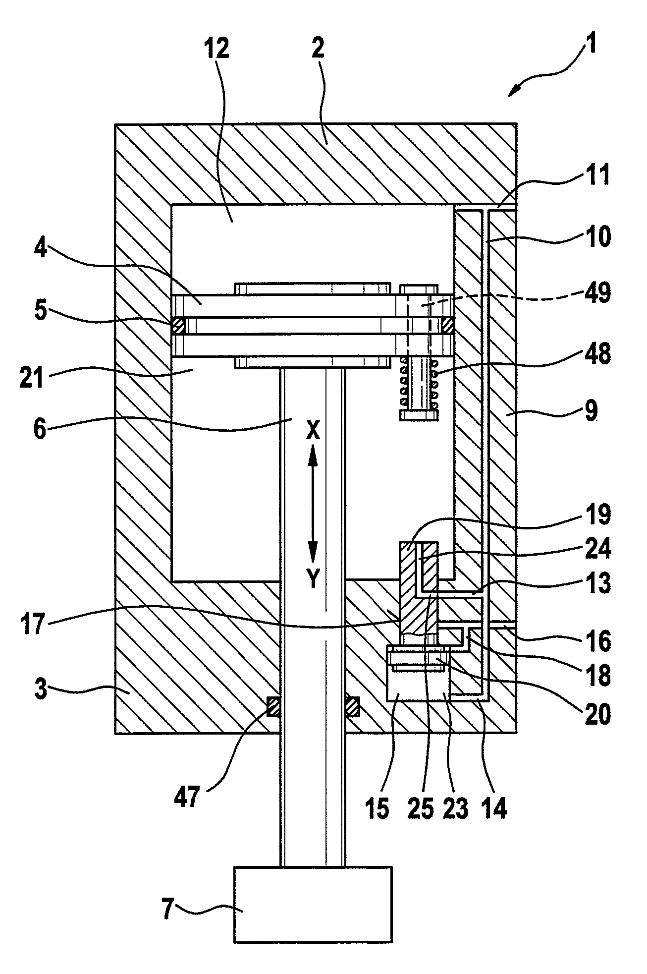
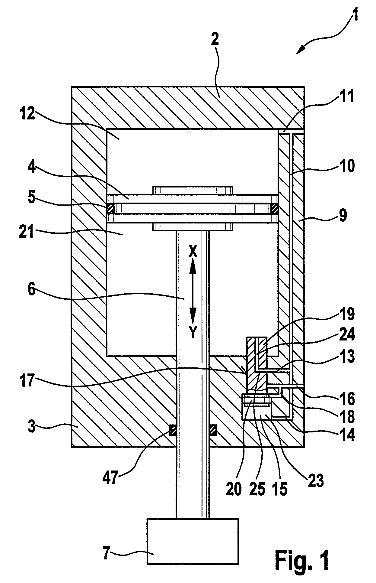
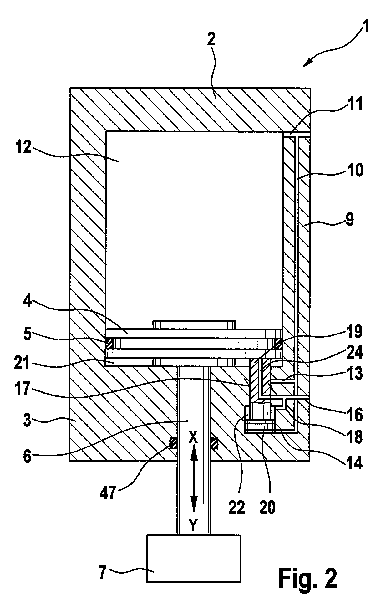
[0031]Shown on the drawing with reference number 1 is a cylinder incorporating a cylinder base 2 and a cylinder cover 3. Cylinder base and / or cylinder cover can be detachably and replaceably connected to the actual cylinder with bolts (not shown).

[0032]Disposed in the cylinder 1 and able to move in a longitudinal direction in opposite directions, that is, in direction X or Y, and sealed with a sealing element 5, is a piston 4. Assigned to the piston 4 on one side is a piston rod 6 via which suitable device parts for tensioning 7, compressing, joining, stamping, embossing, punching and welding are powered. These device parts 7 or the like are indicated in FIGS. 1 and 2 only schematically. Between these device parts 7 a toggle lever arrangement can also be disposed as shown in FIG. 5 and which is marked with the reference number 8. The device part 7 is shown in FIG. 5 by a tensioning arm, which cooperates with other device parts, for example, with an opposing member, also known as a j...


PUM


Abstract

The invention demonstrates how energy saving working cylinders are loaded with fluid under pressure in order, for example, to power devices for tensioning (toggle joint tensioning apparatus), and / or compressing and / or jointing and / or stamping and / or embossing and / or punching and / or welding, if necessary, under the interposition of gearing parts such as guides, parallelogram gears, toggle joint articulations or the like, with the fluid supply being controlled in such a way during the no-load stroke (idle stroke) of the piston (4) that only the forces of inertia and / or weight and / or the forces of friction of moveable parts are overcome and pressure is not applied from the fluid until the power stroke of the piston (4).

Description

BACKGROUND OF THE INVENTION[0001]The invention concerns a procedure for loading a piston-cylinder unit with fluid under pressure, primarily for use in the manufacture of motor vehicle bodywork.[0002]The invention also concerns a control module for loading a piston-cylinder unit with fluid under pressure, primarily for use in the manufacture of motor vehicle bodywork.[0003]The invention also concerns a piston-cylinder unit as a working cylinder to be loaded with fluid under pressure, primarily for use in the manufacture of motor vehicle bodywork.[0004]Finally, the invention concerns the use of a working cylinder of this kind to power devices for tensioning and / or compressing and / or joining and / or stamping and / or embossing and / or punching and / or welding, if necessary, under the interposition of a toggle joint or other gearing parts, e.g. for use in the manufacture of motor vehicle bodywork.[0005]Piston-cylinder units are referred to in the industry for short as “working cylinders”. Wh...

Claims


Application Information

Patent Timeline
Patent Type & Authority Patents(United States)
IPC IPC(8): F15B11/028F15B15/20
CPCB30B15/161F15B11/022F15B11/024F15B13/021F15B15/204F15B2211/3133F15B2211/7053F15B2211/88
Inventor TUNKERS, JOSEF-GERHARD
Owner TUNKERS MASCHENBAU
Learn More