Strength-enhanced water-collecting pan for use under storage hot water heaters

a water-collecting pan and water-collection technology, which is applied in the direction of fluid heaters, functional valve types, lighting and heating apparatus, etc., to achieve the effects of convenient installation, stable installation, and convenient manufactur

Active Publication Date: 2012-01-24
WATERTITE PRODS
View PDF14 Cites 19 Cited by
  • Summary
  • Abstract
  • Description
  • Claims
  • Application Information

AI Technical Summary

Benefits of technology

[0007]It is the primary object of this invention to provide a water-collecting pan of sturdy construction for use in long duration and stable support of an upright storage hot water heater tank having a substantially cylindrical construction, which holds the tank above water that can accumulate as a result of slow leaks and maintenance activity, and allows such water to evaporate and / or drain away from the tank so that the tank can dry out and avoid corrosion and mold that would otherwise shorten its useful life. It is a further object of this invention to provide a water-collecting pan for support of an upright storage hot water heater tank wherein the pan has an integrated structure that allows it to effectively fulfill its intended fluid collection function while resisting permanent deformation, cracking, and / or material weakening as a result handling anticipated during installation, pre-installation transport, and storage. It is also an object of this invention to provide a water-collecting pan for support of an upright storage hot water heater tank that facilitated manufacture and enables stable installation, facilitates installation, shortens installation time, facilitates drain line connection, and requires minimal post-installation inspection and maintenance. A further object of this invention is to provide a water-collecting pan for support of an upright storage hot water heater tank wherein the pan has a nesting structure for compact transport and storage, and provisions to prevent pans from sticking together in stacked array. In addition, it is a further object of the present invention to provide a water-collecting pan for support of an upright storage hot water heater tank wherein the pan is made from crack resistant, corrosion resistant, fire resistant, extremely durable materials that resist premature deterioration and malfunction, as well as have resistance to temperature extremes.
[0008]The present invention, when properly made and used, will provide a water-collecting pan of sturdy construction and resilient materials that can be used for reliable long-term support of a storage hot water heater tank in an elevated position above fluids accumulating below it as a result of slow leaks or maintenance activity, and which further directs water away from the hot water heater tank to allow it to dry out and reduce premature deterioration of its exterior surface. Reduced risk of damage to surroundings is also a benefit of present invention pan use. However, due in part to the space limitations typically encountered at hot water heater tank installation sites, it is not contemplated for the water-holding capacity of the present invention pan to be big enough to hold the entire water volume present in a supported hot water heater tank at once, should catastrophic failure of the tank occur. A central hub and arcuate spokes connected thereto, which are integral to the present invention pan's bottom surface, substantially fill the pan's center portion to more rapidly direct fluid accumulating in the non-raised areas between spokes toward switch / drain connections on the surrounding perimeter wall. The hub connection is desired to prevent the spokes from twisting and allows the manufacture of larger present invention pans for use under larger capacity storage tanks. Spokes also have a convex top surface and outwardly-and-downwardly sloping sides / walls that prevent fluid accumulation thereon, as well as improve fluid flow around them to facilitate communication between the various water collection areas in the pan and avoid excess water collection in any one portion of the pan's bottom surface. The arcuate perimeter configuration of the spokes also avoids the formation of pressure points during the pan's manufacture, which could otherwise develop into cracks in the pan material during pre-installation handling or use. The sloping and arcuate surfaces in the spokes further allow as much material as is needed to be pulled from a single sheet of plastic, without causing weak points. In fact, none of the vertically-extending surfaces of the present invention pan has a precisely vertical orientation, including the sides of the central hub, spokes, and both types of risers (which are all downwardly-and-outwardly sloping), and the perimeter wall and its upturned lip (which are each upwardly-and-outwardly inclined).
[0009]Two types of risers in the present invention pan further strengthen it, with each type of riser having a different height dimension from the other that pulls just enough material during manufacture to prevent pressure points between them that might otherwise lead to the development of cracks in the pan material during its handling and extended use in supporting a heavy hot water heater tank. Reinforcement structure is also provided between each riser and the perimeter wall for the same purposes. Furthermore, the perpendicular orientation of the smaller low elevation risers to the taller risers allows an installer to slide a hot water heater across The substantially circular perimeter wall of the present invention pan also has an upturned lip that provides additional fluid-collection depth that extends upwardly above the top surfaces of the hub, spokes, and risers. It is further contemplated in the most preferred embodiments of the present invention for the central hub, spokes, and risers to each have a nesting configuration for compact storage and transport of pans in stacked array. Small indents of varying mismatched configuration can also be used in the upturned lip to prevent adjacent pans from sticking together during their storage and transport. Thus, each successive pan placed into a stack of pans can then be rotated relative to the one above it, as well as relative to the one below it, to facilitate removal of one or more pans from a stack, when needed. Furthermore, although the present invention is primarily contemplated for use in hot water heater applications to avoid damage and accelerated tank deterioration from slow leaks, it also may be used in other applications where rising fluid beyond a threshold limit is undesirable and prompt notification thereof is needed to eliminate the risk of property damage. Many switches are known that respond to a very small amount of water accumulation, and can be associated with the present invention pan for such purposes. Since the fluid collecting pan of the present invention is made from corrosion-resistant plastic materials, premature deterioration and malfunction thereof due to corrosion are avoided.
[0010]The present invention pan materials are also fire resistant and resistant to failure as a result of exposure to temperature extremes, so that installation in unheated basements, garages, and / or laundry rooms detached from main residence areas is possible. The perimeter wall of the present invention pan is also sufficiently sturdy and may be configured for effective use with fluid-level detection devices and alarms. Thus, since a storage hot water heater tank is supported on vibration isolators secured to the top surfaces of the risers in a present invention pan, air circulation space exists directly under its exterior bottom surface, which after exposure to water is then allowed to dry out, reducing the risk of corrosion and mold, and helping to reduce maintenance issues so as to prolong its useful life.

Problems solved by technology

However, due in part to the space limitations typically encountered at hot water heater tank installation sites, it is not contemplated for the water-holding capacity of the present invention pan to be big enough to hold the entire water volume present in a supported hot water heater tank at once, should catastrophic failure of the tank occur.

Method used


Image

  • Strength-enhanced water-collecting pan for use under storage hot water heaters
  • Strength-enhanced water-collecting pan for use under storage hot water heaters
  • Strength-enhanced water-collecting pan for use under storage hot water heaters

Examples


Embodiment Construction

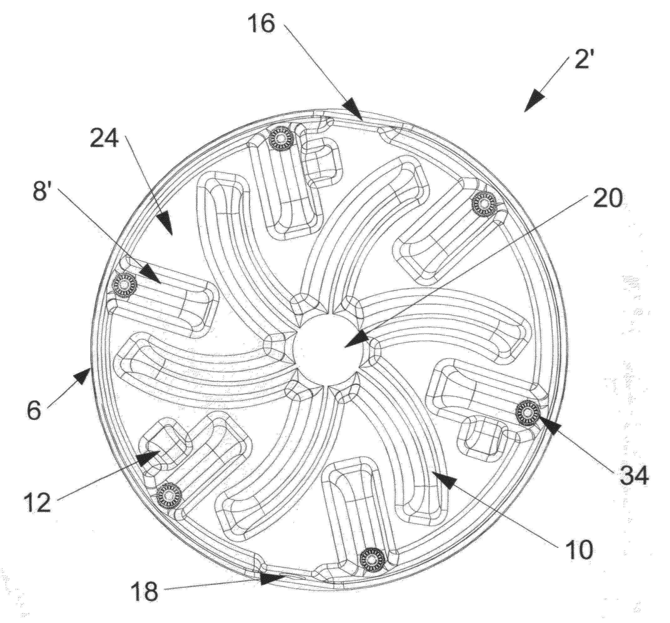
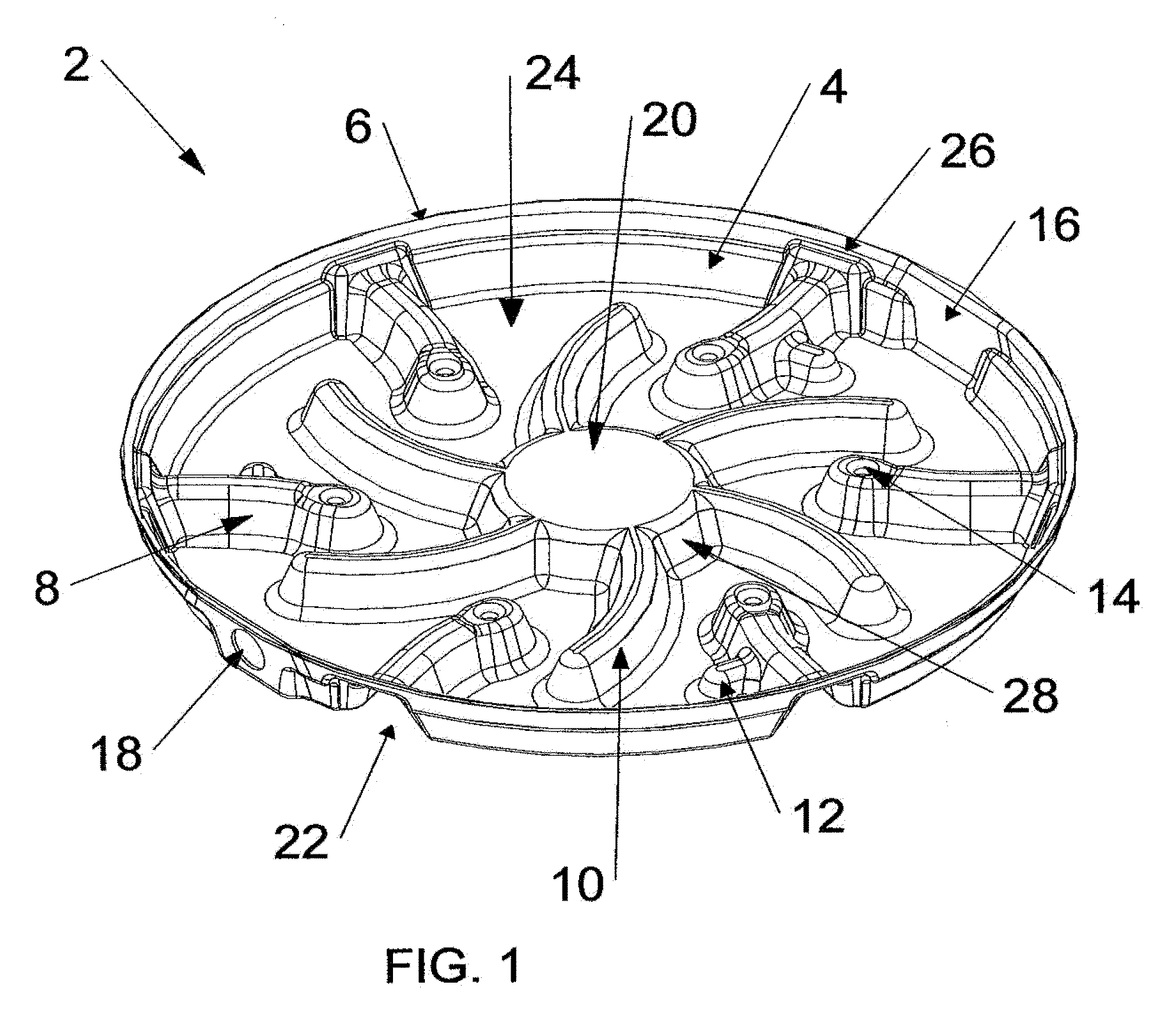
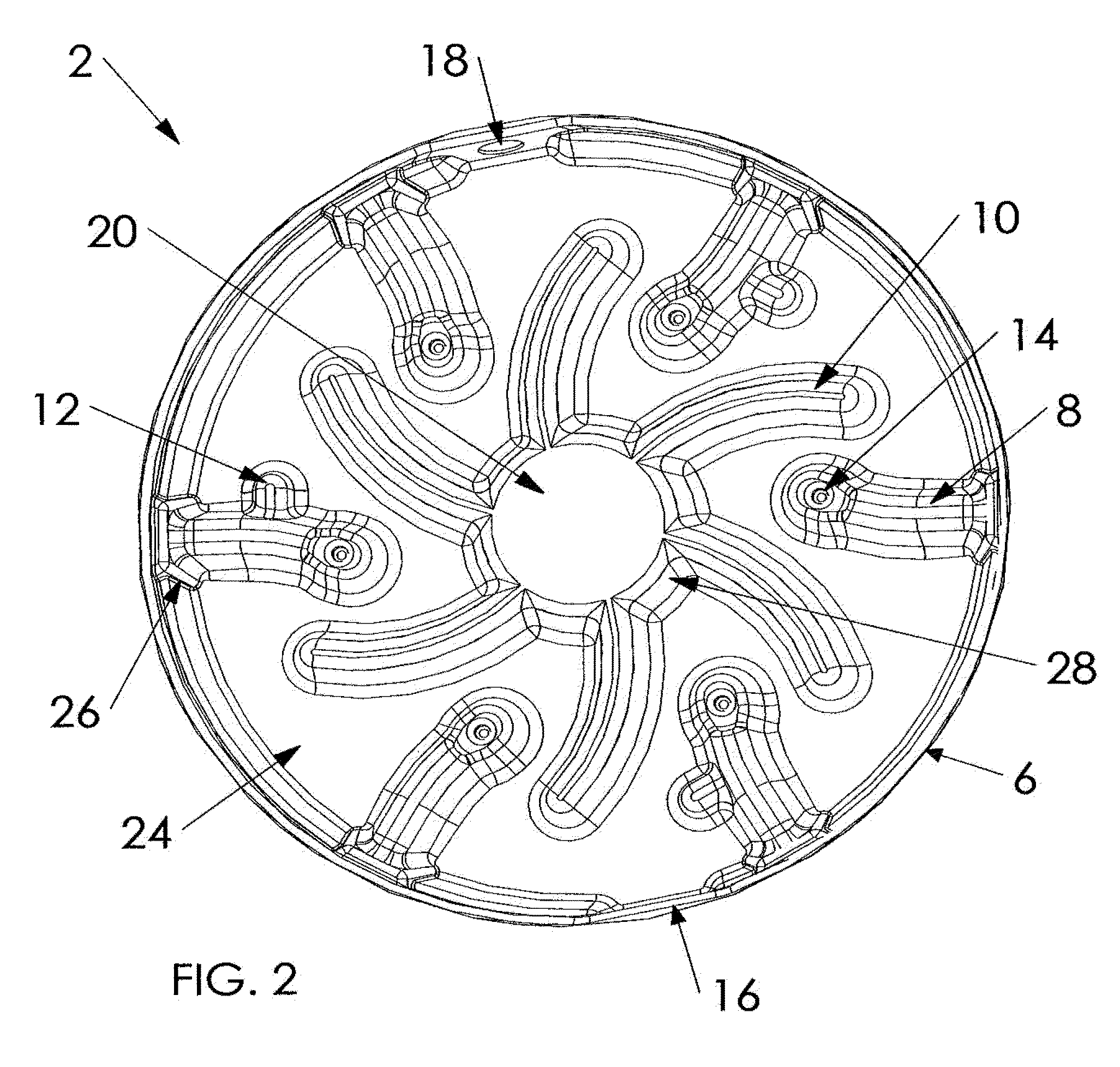
[0041]The present invention is a sturdy fluid-collecting pan (2, 2′ or other) primarily for placement under a cylindrical storage hot water heater tank 32 (such as that shown in FIG. 7) in an upright orientation, and support thereof in a stable and fixed position during its use, wherein the present invention pan has a multi-level construction with a non-raised bottom water-collection surface 24 having a substantially circular perimeter, a perimeter wall (4, 4′ or other) surrounding bottom water-collection surface 24, with an upturned lip 6 upwardly-depending from perimeter wall (4, 4′ or other), a drain opening 18 through one part of perimeter wall 4, a flattened area 16 of comparable size and configuration on perimeter wall 4 in a position opposed to drain opening 18 that improves the nesting capability of multiple pans 2 in stacked array, a raised hub 20 integral with the center portion of bottom water-collection surface 24, spaced-apart pan-strengthening and fluid-dispersing rais...


PUM


Abstract

A multi-level fluid-collecting pan configured for placement under an upright cylindrical hot water heater tank and support thereof. It has a circular bottom surface integral with a raised central hub, multiple raised arcuate spokes extending outwardly from the hub, and multiple elevated risers extending from the perimeter wall toward the hub. A perimeter wall around the bottom surface defines a non-raised fluid-collecting area. Vibration isolators that support a hot water heater tank upon the risers maintain the tank above any accumulated water in the non-raised areas of the bottom surface. Low elevation risers in perpendicular orientation to some risers, a nesting configuration with mismatched indents, sturdy and impact-resistant materials, a drain opening in the perimeter wall, and an upturned lip extending upwardly from the perimeter wall, are also preferred. The hub, spokes, and risers cover much of the pan's bottom surface and force accumulated water toward the perimeter wall.

Description

CROSS-REFERENCES TO RELATED APPLICATIONS[0001]None.BACKGROUNDField of the Invention[0002]This invention relates to stands for hot water heater tanks that are maintained in an upright orientation to store heated water in a ready-to-use condition, specifically to a water-collecting pan configured for placement under an upright storage hot water heater tank wherein an integrated multi-level bottom structure in the pan includes a centrally located star pattern comprising a center hub and multiple arcuate spokes radiating therefrom. The integrated pan structure also includes a plurality of risers each having substantially even height dimension to that of the hub and spokes, and positioning between adjacent spokes without contact with the hub or spokes. Risers depend from the perimeter wall surrounding the hub and spokes, and extend inwardly toward the hub, and if they have an arcuate perimeter configuration that creates a shorter side, it is preferred for the shorter sides of arcuate ris...

Claims


Application Information

Patent Timeline
Patent Type & Authority Patents(United States)
IPC IPC(8): B65D1/34
CPCF24H9/06F24H9/165Y10T137/5762F24H9/17
Inventor CANTOLINO, CHRISTOPHER RALPH
Owner WATERTITE PRODS
Why Eureka
Try Eureka