Water supply control assembly with automatic shut-off and duty cycle reset

a technology of water supply control and automatic shut-off, applied in the direction of process and machine control, liquid/fluent solid measurement, motor/generator/converter stopper, etc., can solve the problem of water leakage of some degree and remain likely to occur, so as to save water and minimize property damage

Inactive Publication Date: 2012-01-24
SLUPECKI RAYMOND H +1
View PDF16 Cites 23 Cited by
  • Summary
  • Abstract
  • Description
  • Claims
  • Application Information

AI Technical Summary

Benefits of technology

[0008]Even though plumbing equipment of the highest quality may be inspected, maintained and replaced according to a conservative schedule, water leakage of some degree remains likely to occur and should be guarded against because of the possibility of human error, accidents, acts of nature, hidden defects and malicious acts. In keeping with the desire to minimize property damage and conserve water, the water control apparatus presented herein, when coupled to a water supply line, provides a compromise solution in which a small, limited amount of water leakage resulting from such unforeseeable or uncontrollable causes is tolerated only for a short time interval in exchange for a positive and total shut-off of water service.

Problems solved by technology

Even though plumbing equipment of the highest quality may be inspected, maintained and replaced according to a conservative schedule, water leakage of some degree remains likely to occur and should be guarded against because of the possibility of human error, accidents, acts of nature, hidden defects and malicious acts.

Method used


Image

  • Water supply control assembly with automatic shut-off and duty cycle reset
  • Water supply control assembly with automatic shut-off and duty cycle reset
  • Water supply control assembly with automatic shut-off and duty cycle reset

Examples


Embodiment Construction

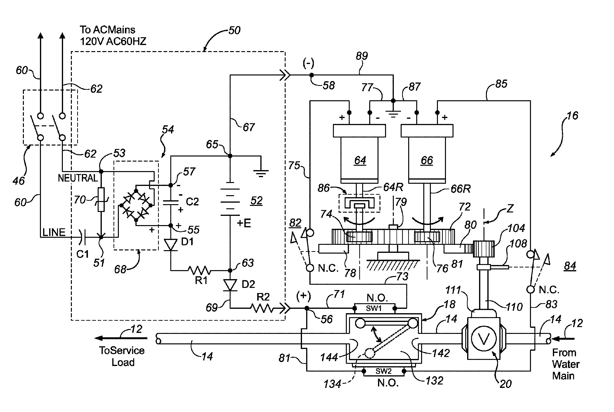
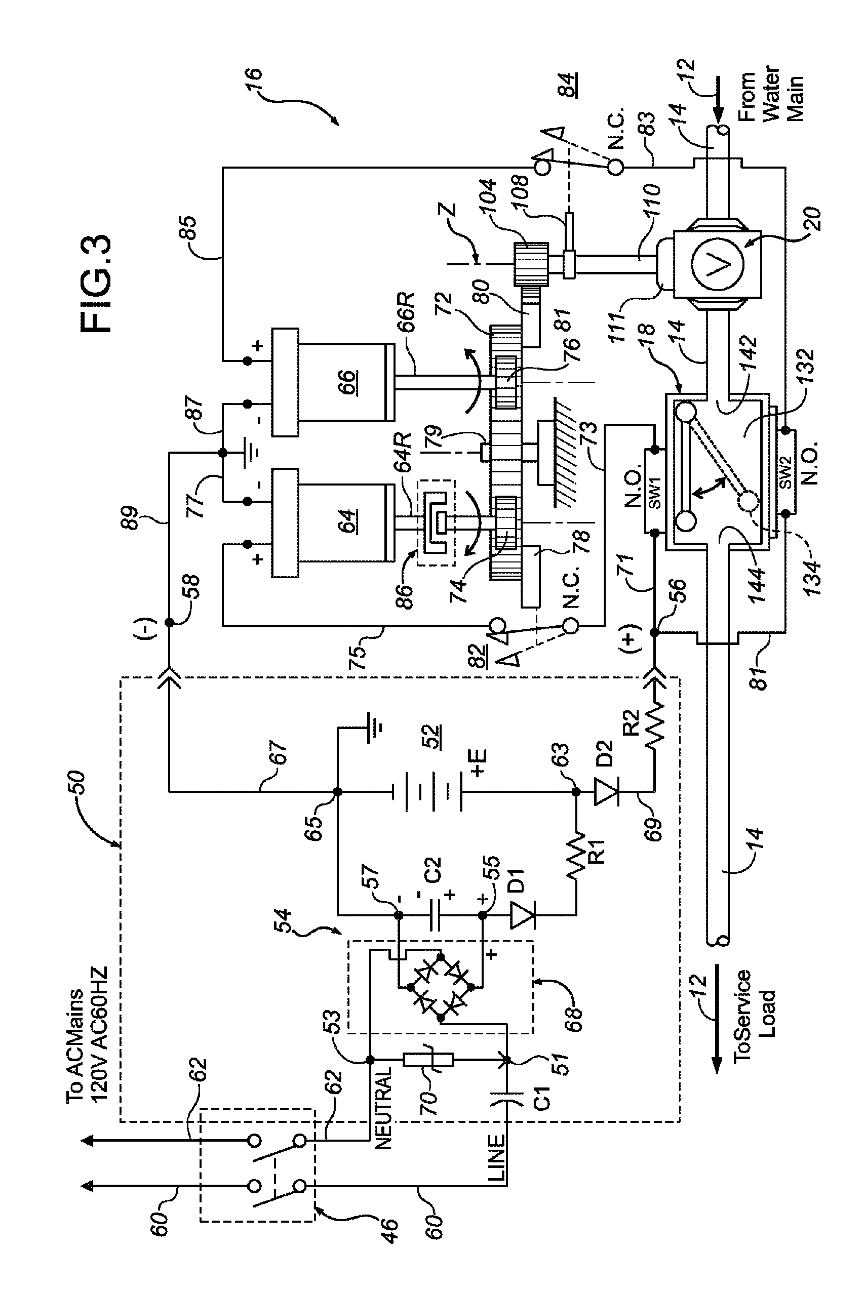
[0019]While the making and using of various embodiments of the present invention are discussed in detail below, it should be appreciated that the present invention provides many applicable inventive concepts which can be embodied in a wide variety of specific contexts. The specific embodiments discussed herein are merely illustrative of specific ways to make and use the invention, and do not delimit the scope of the present invention.

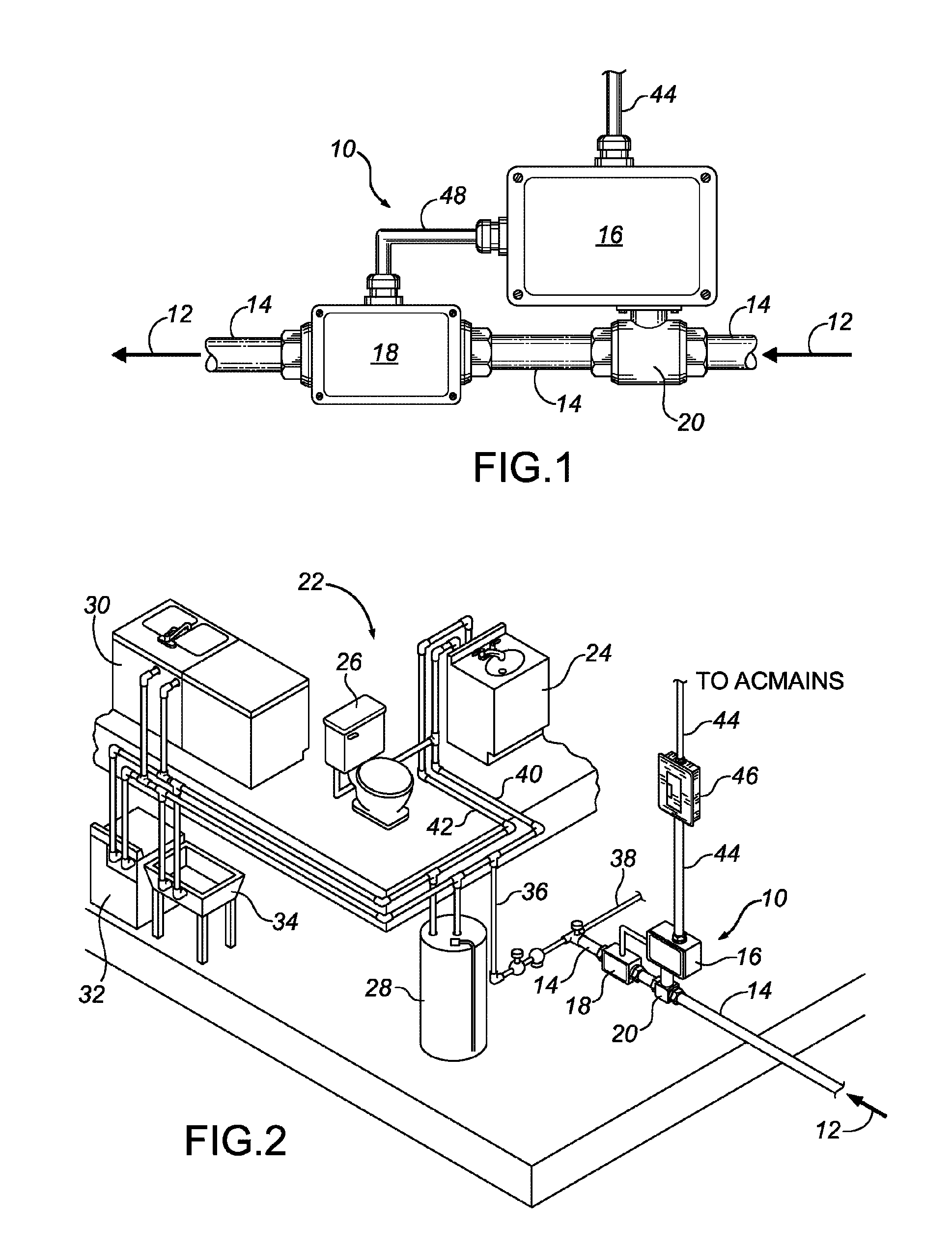
[0020]FIGS. 1 and 2 illustrate one embodiment of a fluid flow control system 10 installed in a domestic water supply system of a single family house which is similar to that found in many homes today. The water supply system 10 receives pressurized water 12 from a public water service utility through an incoming water line 14. The incoming water line 14 passes through a basement wall of the house to supply water to two distribution branches 36 and 38 of the cold water supply.

[0021]As illustrated, branch 36 supplies cold water to the building's hot water...


PUM


Abstract

A water supply control assembly is disclosed for cutting off the supply of water to a house or building in the event of excessive water consumption. In one embodiment, a valve is secured to a distribution conduit in fluid communication with a pressurized source of fluid. A water flow sensing unit is secured between the inlet port and the flow discharge port. A magnet is mounted therein to a displaceable member and moved into and out of magnetic field coupling proximity to a timing reed switch in response to the onset and termination of pressurized water flow through the water flow sensing unit. A controller is coupled to the timing reed switch in order to actuate the valve to a water shut-off condition in response to the continuous flow of pressurized water for an elapsed flow time in excess of a preset duty cycle limit.

Description

TECHNICAL FIELD OF THE INVENTION[0001]This invention relates, in general, to water supply and, in particular, to a water supply control valve assembly which cuts off the supply of water to a house or building in the event of excessive water consumption caused by a leak, plumbing break or open faucet.BACKGROUND OF THE INVENTION[0002]Catastrophic property damage often occurs in a home or office building as the result of runaway water leakage from a broken or badly leaking water supply line. Since water supply lines generally run throughout a house or building and are concealed behind wall panels, an uncontrolled water leak may result in extensive damage both to the building structure and its contents before the leak is detected. Some typical causes of runaway water leakage are ruptured pipes and loose plumbing; worn-out washing machine hoses, rusted water heaters, aging plumbing fittings, failure of automatic lawn sprinklers and other landscape irrigation equipment, component failure ...

Claims


Application Information

Patent Timeline
Patent Type & Authority Patents(United States)
IPC IPC(8): F16K17/00
CPCE03B7/071F16K5/0615F16K31/042F16K37/005G01F1/28G01F13/006G01F15/001G05D7/0635F16K37/0041Y10T137/7723Y10T137/7727Y10T137/8208Y02A20/15
Inventor SLUPECKI, RAYMOND H.MILLER, J. THOMAS
Owner SLUPECKI RAYMOND H
Why Eureka
Try Eureka