
Semiconductor device and the method of manufacturing the same

a semiconductor and semiconductor technology, applied in semiconductor devices, semiconductor/solid-state device details, electrical devices, etc., can solve the problems of large warps in thin silicon wafers, high manufacturing costs, and cracks that are liable to be caused in sin films, so as to facilitate the improvement of the moisture resistance of the exposed portion, and reduce the failure of cracks. , the effect of excellent moisture resistan

Active Publication Date: 2012-01-24
FUJI ELECTRIC CO LTD
View PDF3 Cites 0 Cited by
  • Summary
  • Abstract
  • Description
  • Claims
  • Application Information

AI Technical Summary

Benefits of technology

The invention provides a semiconductor device with improved moisture resistance and prevention of failures caused by cracks and Si nodule growth. The device includes a metal electrode wiring laminate with a barrier metal laminate and an aluminum film or aluminum alloy film. An organic passivation film covers the metal electrode wiring laminate for added protection. The method of manufacturing the semiconductor device involves patterning the aluminum film or aluminum alloy film with a predetermined wiring pattern, etching the residue remaining on the exposed surface of the barrier metal laminate, and coating an organic passivation film. The metal electrode wiring laminate includes a three-layered barrier metal laminate, formed of a Ti film, a TiN film, and a Ti film, and an Al film or Al—Si alloy film laminated on the three-layered barrier metal laminate. The invention prevents the growth of Si nodules and cracks caused by heat treatment and wire bonding, reducing failures in the semiconductor device.

Problems solved by technology

Although the SiN film exhibits excellent moisture resistance, defects such as cracks are liable to be caused in the SiN film by the surface stress due to the thermal expansion coefficient difference between the SiN film and the silicon substrate.
The formation of two passivation films makes the manufacturing costs soar inevitably.
When the SiN film is combined a thin silicon wafer, a large warp is caused in the thin silicon wafer.
It is impossible to make the warped silicon wafer flow through the subsequent manufacturing steps.
The large Si nodules cause start points in the SiN film, from which cracks are caused in the wire bonding step in the assembly process, further causing failure increase.

Method used


Image

  • Semiconductor device and the method of manufacturing the same
  • Semiconductor device and the method of manufacturing the same
  • Semiconductor device and the method of manufacturing the same

Examples


Embodiment Construction

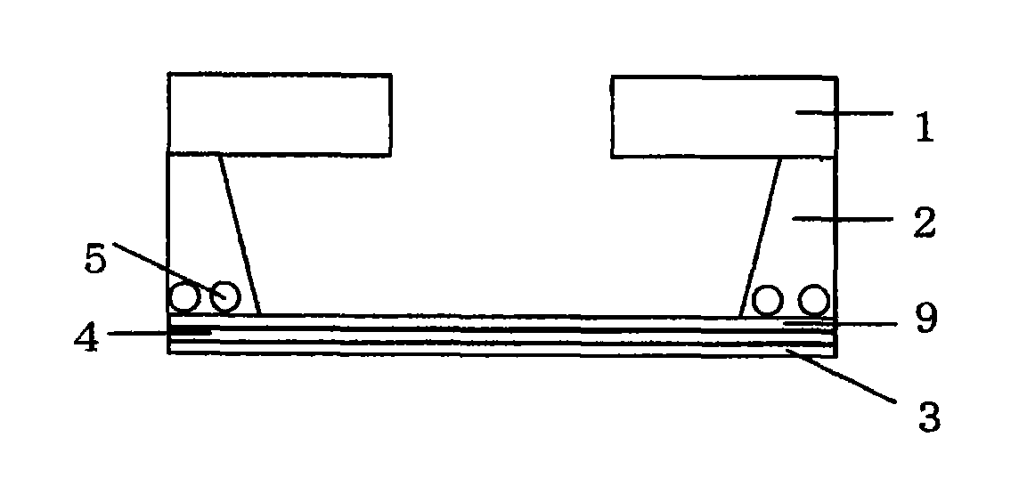
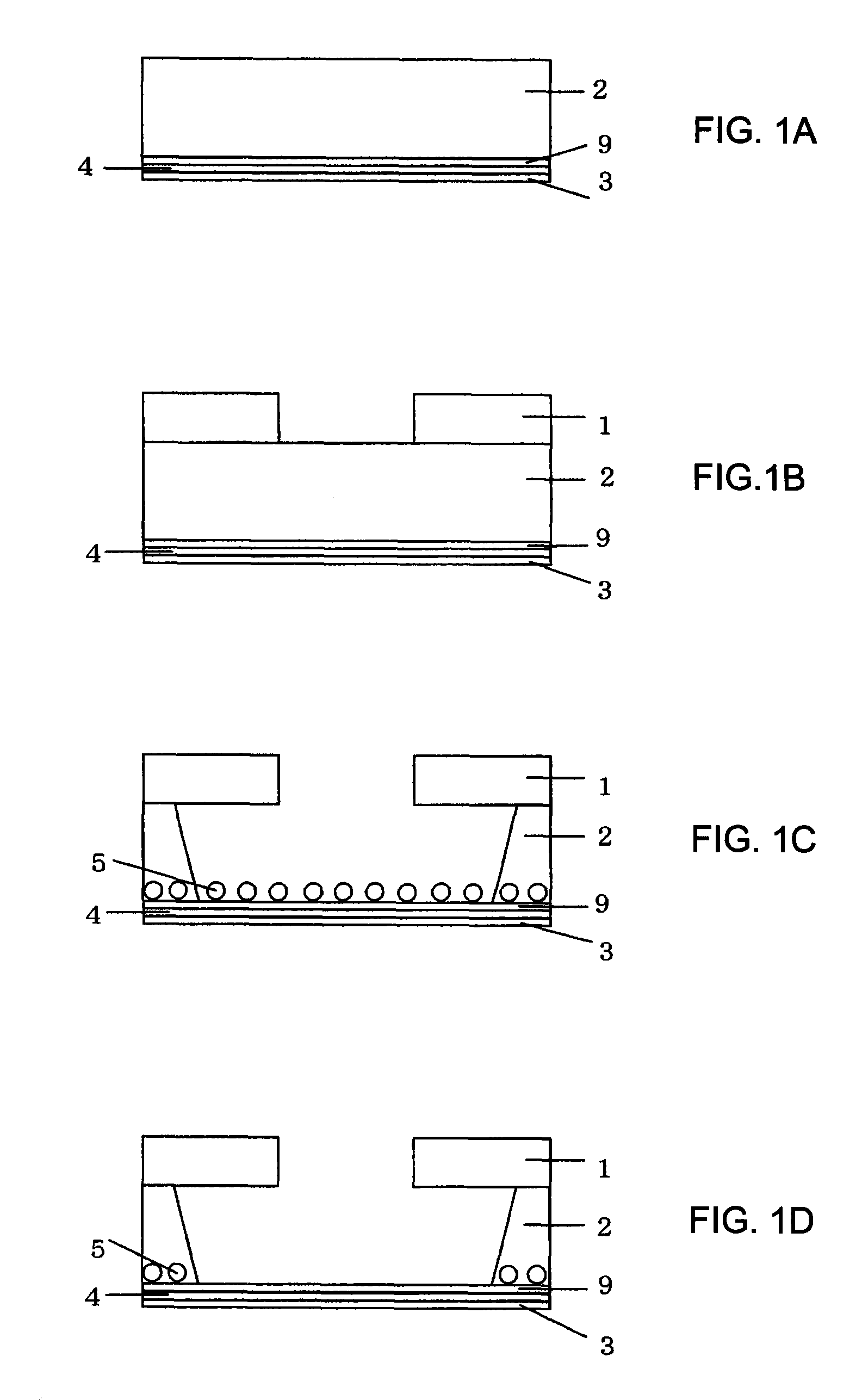
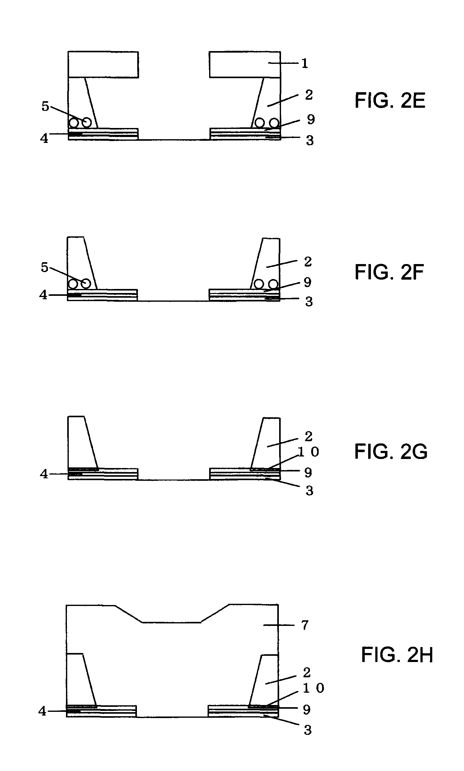
[0024]Now the process flow for manufacturing the semiconductor device according to a first embodiment that includes a metal electrode wiring laminate including a barrier metal laminate, formed of a Ti film, a TiN film on the Ti film, a Ti film on the TiN film, and an Al—Si film on the barrier metal laminate will be described below with reference to FIGS. 1(a) through 1(d) and FIGS. 2(e) through 2(h). The semiconductor device and the manufacturing method thereof according to the first embodiment are the same with the conventional semiconductor device and the conventional manufacturing method thereof in many aspects. Therefore, duplicated descriptions on the semiconductor device and the manufacturing method thereof according to the first embodiment will be avoided. In other words, the semiconductor device and the manufacturing method thereof according to the first embodiment will be described mainly in connection with the differences thereof from the semiconductor device that includes...


PUM

PropertyMeasurementUnit
thicknessaaaaaaaaaa
thicknessaaaaaaaaaa
pressureaaaaaaaaaa

Abstract

A semiconductor device includes a semiconductor substrate; a metal electrode wiring laminate on the semiconductor substrate, the metal electrode wiring laminate being patterned with a predetermined wiring pattern; the metal electrode wiring laminate including an undercoating barrier metal laminate and aluminum or aluminum alloy film on the undercoating barrier metal laminate; and organic passivation film covering the metal electrode wiring laminate, wherein the barrier metal laminate is a three-layered laminate including titanium films sandwiching a titanium nitride film. The semiconductor device according to the invention facilitates improving the moisture resistance of the portion of the barrier metal laminate exposed temporarily in the manufacturing process, facilitates employing only one passivation film, facilitates preventing the failures caused by cracks from occurring and the failures caused by Si nodules remaining in the aluminum alloy from increasing.

Description

BACKGROUND OF THE INVENTION[0001]The present invention relates to a semiconductor device used in semiconductor integrated circuits and the method for manufacturing the semiconductor device. Specifically, the invention relates to a semiconductor device that has a multilayered electrode structure including a metal electrode wiring laminate formed on a semiconductor substrate and having a predetermined wiring pattern. The metal electrode wiring laminate includes an undercoating barrier metal laminate and an aluminum film or an aluminum alloy film formed on the undercoating barrier metal laminate. The metal electrode wiring laminate is covered with a passivation film. Specifically, the invention further relates to the method for manufacturing the semiconductor device having the multilayered electrode structure described above.[0002]The method for manufacturing the semiconductor device having a conventional multilayered electrode structure will be described below focusing especially on t...

Claims


Application Information

Patent Timeline
Patent Type & Authority Patents(United States)
IPC IPC(8): H01L23/48
CPCH01L24/03H01L24/04H01L24/48H01L2924/01004H01L2924/01013H01L2924/01014H01L2924/01022H01L2924/0105H01L2924/01061H01L2924/01074H01L2924/04941H01L2924/14H01L2924/3511H01L2924/01005H01L2924/01006H01L2924/01033H01L2924/01045H01L2224/48H01L2924/10253H01L2924/00H01L2924/00014H01L2224/45099H01L2224/45015H01L2924/207
Inventor SASAKI, KOJIMATSUZAKI, KAZUOKOBAYASHI, TAKASHI
Owner FUJI ELECTRIC CO LTD
Learn More