Multiple device apparatus, systems, and methods

a multi-device, multi-device technology, applied in the direction of instruments, coding, code conversion, etc., can solve the problems of reducing the number of channels over which information is transmitted, and reducing the bandwidth used to transmit information to multiple devices. , to achieve the effect of increasing the amount of useful information, reducing the bandwidth used to transmit information, and increasing efficiency

Active Publication Date: 2012-01-24
MICRON TECH INC
View PDF15 Cites 64 Cited by
  • Summary
  • Abstract
  • Description
  • Claims
  • Application Information

AI Technical Summary

Problems solved by technology

This reduces the bandwidth used to transmit information to multiple devices and may reduce the number of channels over which the information is transmitted.
This reduces the bandwidth used to transmit the information to multiple devices and may reduce the number of channels over which the information is transmitted.

Method used


Image

  • Multiple device apparatus, systems, and methods
  • Multiple device apparatus, systems, and methods
  • Multiple device apparatus, systems, and methods

Examples


Embodiment Construction

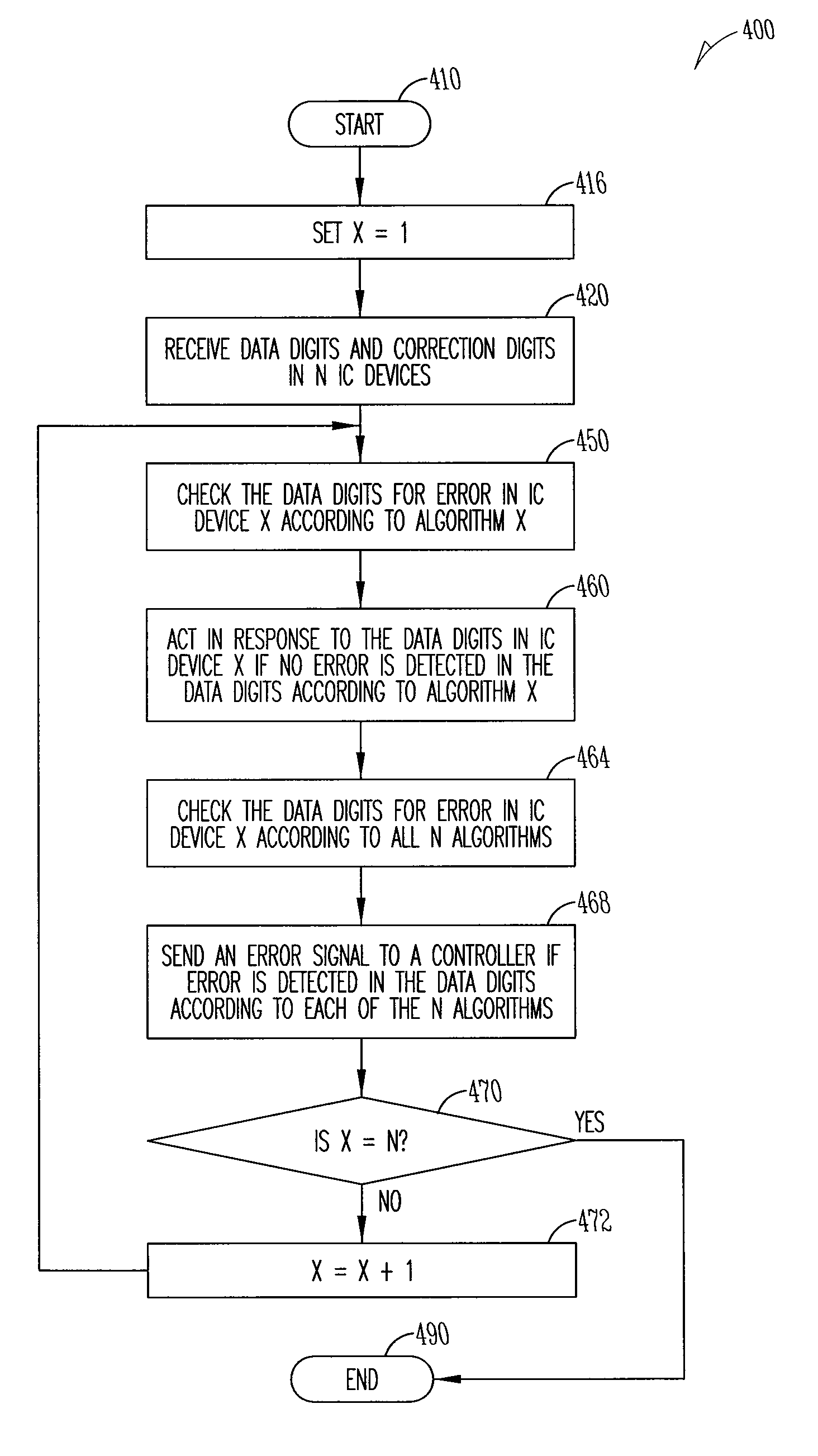
[0009]Systems including multiple devices typically receive information in the form of data digits. Some of the data digits, called chip select digits, select the device that is to receive and act on the information. The chip select digits take up bandwidth and may be communicated on dedicated channels between the devices. If the data digits are transmitted in packets, the chip select digits may result in the packet having a non-binary length. In addition, read data packets do not include chip select digits, while write data packets do include chip select digits.

[0010]The inventor has discovered that the challenges noted above, as well as others, can be addressed by encoding correction digits differently depending on the device being addressed. Encoding correction digits to select a device to receive and act on the data digits transmitted as well as to provide a capability to detect and correct errors in the data digits makes it unnecessary to send separate chip select digits. This r...


PUM


Abstract

Data digits and correction digits are received in each of a number of integrated circuit (IC) devices. Apparatus, systems, and methods are disclosed that operate to check the data digits for error in each IC device according to an algorithm associated with the IC device, the algorithm being different for each IC device. Each IC device will act in response to the data digits if no error is detected in the data digits. Additional apparatus, systems, and methods are disclosed.

Description

BACKGROUND[0001]Integrated circuit (IC) devices, including memory devices, are often used in computers and other electronic products (e.g., digital televisions, digital cameras, and cellular phones) to store data and other information. Multiple IC devices are often used together in a system.BRIEF DESCRIPTION OF THE DRAWINGS[0002]FIG. 1 is a block diagram of a system according to various embodiments of the invention.[0003]FIG. 2A illustrates a data structure of a command packet used in the system shown in FIG. 1, according to various embodiments of the invention.[0004]FIG. 2B illustrates a data structure of a data packet used in the system shown in FIG. 1, according to various embodiments of the invention.[0005]FIG. 3 is a flow diagram of a method according to various embodiments of the invention.[0006]FIG. 4 is a flow diagram of a method according to various embodiments of the invention.[0007]FIG. 5 is a block diagram of a system according to various embodiments of the invention.[00...

Claims


Application Information

Patent Timeline
Patent Type & Authority Patents(United States)
IPC IPC(8): G06F11/00
CPCG06F11/1004H03M13/09H03M13/1102H03M13/136H03M13/15H03M13/1515H03M13/152H03M13/19H03M13/2957
Inventor HARGAN, EBRAHIM H
Owner MICRON TECH INC
Why Eureka
Try Eureka