[0004]By means of the separation grid, the region above the intermediate plate is divided into a plurality of segments, and, by rotation of the intermediate plate, the granular material is then enabled to fall through the through-opening into the intermediate plate. Owing to the segmentation of the surface above the intermediate plate, bridging of the granular material is prevented.
[0010]The through-opening is preferably a slot extending in a radial direction of the intermediate plate. In a further advantageous embodiment, a plurality of slots of this kind may also be provided. The provision of these slots enables an extremely uniform discharging of the granular material. The through-opening preferably essentially extends along essentially the entire radial length of the intermediate plate, so that the granular material can pass through the intermediate plate in the entire radial region. To increase stability, lugs which join together the edges of the slots may also be provided.
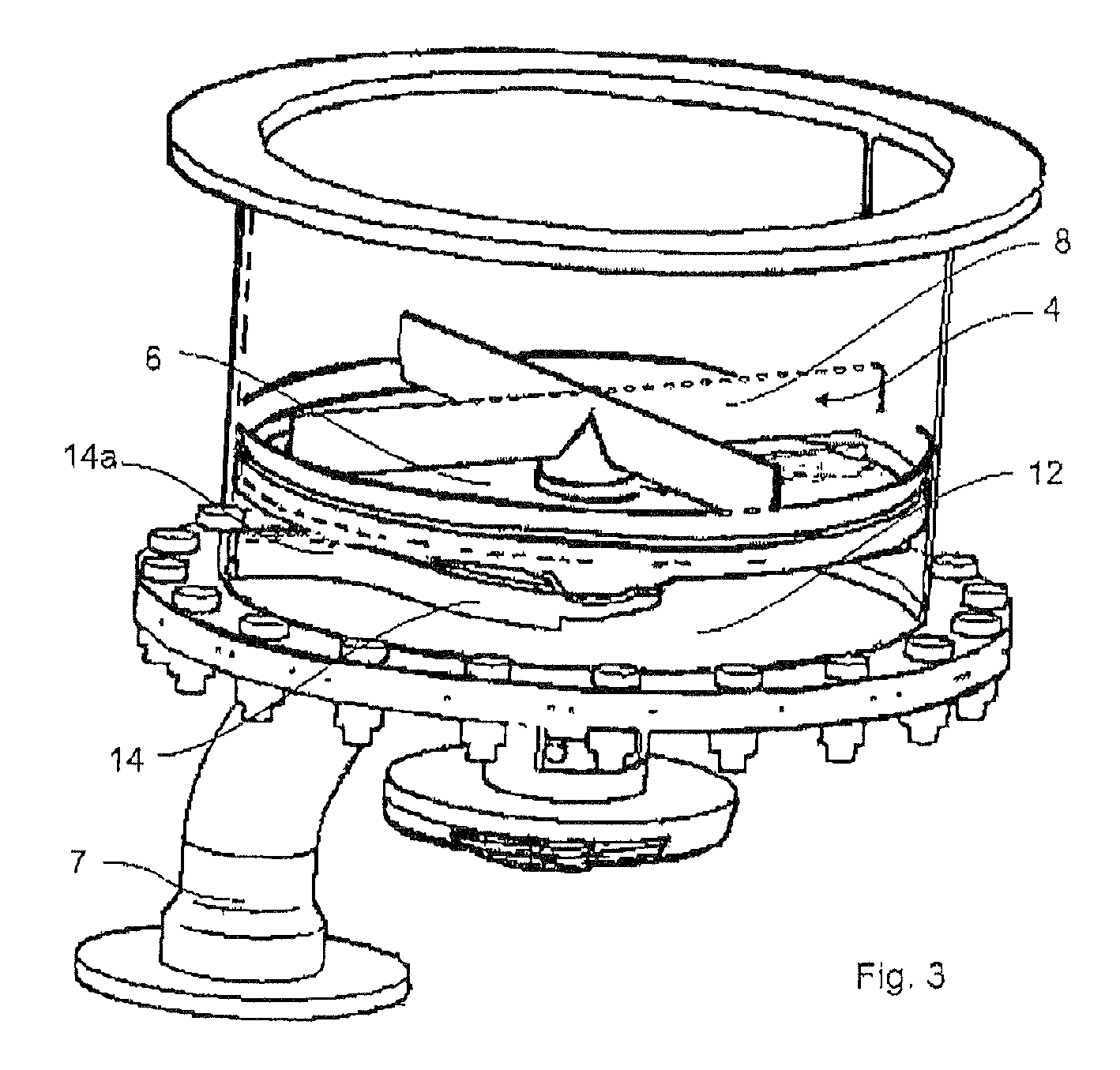
[0012]Before the through-opening in the direction of rotation, the intermediate plate is equipped, in the case of a further advantageous embodiment, with an oblique surface, which preferably conceals the through-opening located beneath this oblique surface. As already mentioned, the rotating intermediate plate may be equipped with one or more
discharge slots. In this manner, the direct slippage of the granular material through the intermediate plate is prevented, and during the rotation of the intermediate plate, this oblique surface serves to compact the granular material immediately before the oblique surface or ramp, so that material compressed in this manner is pressure-relieved after the ramp and falls through the intermediate plate into the
discharge chamber. The oblique surface or ramp is preferably inclined between 20° and 30° relative to the plane of the intermediate plate.
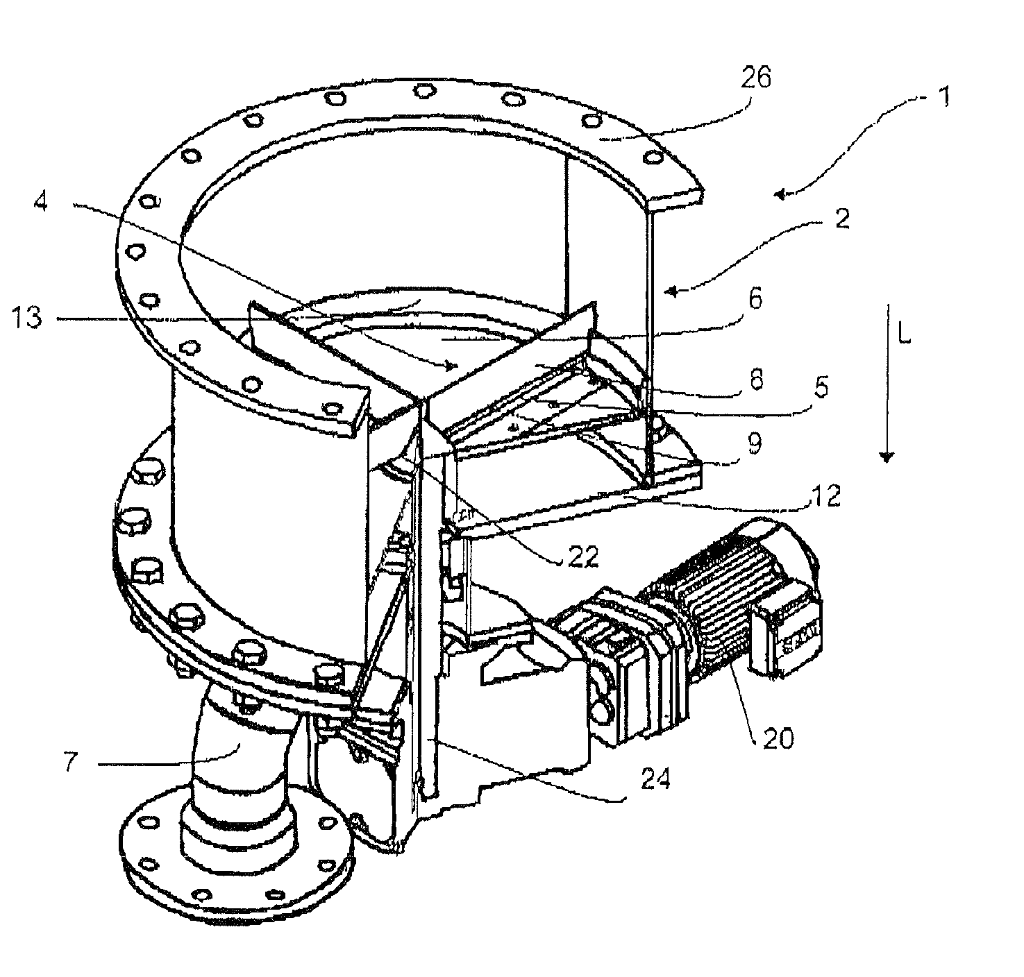
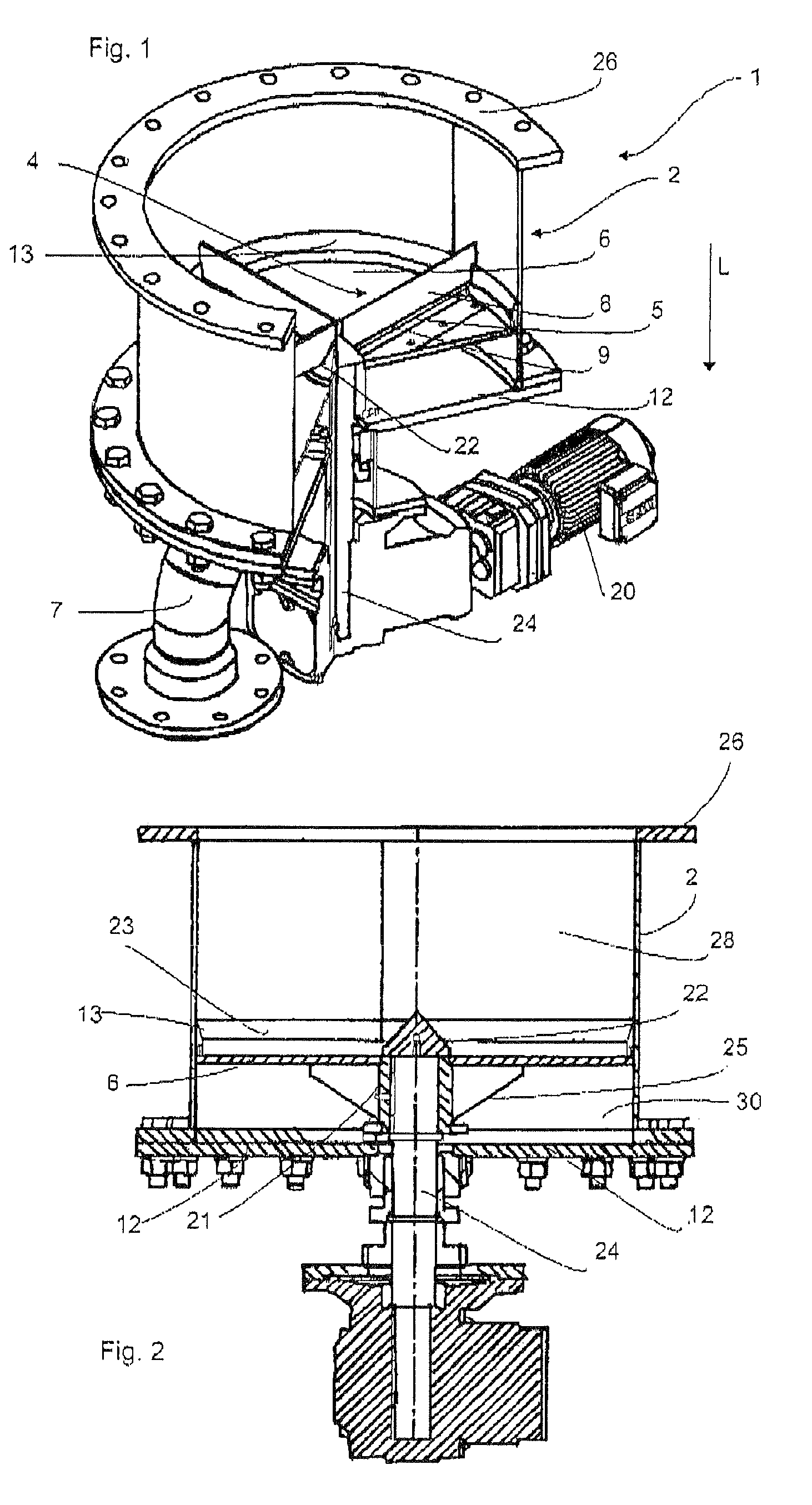
[0015]In the case of a further advantageous embodiment, the separation grid is equipped with between three and twelve arms, between four and ten being preferred and between four and eight being especially preferred, which arms extend in the radial direction of the intermediate plate. These arms or perpendicular panels, disposed radially, preferably taper towards the top in order to prevent any bridging. The smaller the quantity of these arms or panels, the greater the tendency towards reverse-mixing of the granular material. The greater the quantity of these arms or panels, however, the greater the risk of bridging in the device. The spacing of these arms is thus preferably matched to the granular material, and in this manner any
mastication or pulping of the granular material or the co-rotation thereof is prevented, thereby conserving the product. It is further possible to dispose the arms obliquely relative to the intermediate plate.
[0016]The separation grid is preferably disposed at a distance from the intermediate plate. The emptying of the intermediate plate thus takes place by scraping, and in this manner, the core flow is minimised. It is also possible to arrange the removal of the granular material from the receptacle by the first-in-first-out principle. Use for all types of time-controlled processes in reactors is also conceivable. The distance between the arms and the intermediate plate is preferably between 10 mm and 20 mm.
[0017]In the case of a further advantageous embodiment, the device is equipped with a conical distributing element which is centrally disposed above the intermediate plate. It is especially preferred for this conical element to be disposed in a manner such that its
axis of symmetry coincides with the
axis of symmetry of the intermediate plate. This cone enables the virtually complete emptying of the
silo, which is advantageous, in particular, in processes in which product changes are necessary. This conical element preferably rotates jointly with the intermediate plate.

