Method and ionizer for bipolar ion generation

a bipolar ion and ionizer technology, applied in the direction of ion beam tubes, tubes with electrostatic control, instruments, etc., can solve the problems of affecting the efficiency of ion generation, unisonization, and large number of needles, and occupying a large spa

Active Publication Date: 2012-01-31
FILT AIR
View PDF17 Cites 40 Cited by
  • Summary
  • Abstract
  • Description
  • Claims
  • Application Information

AI Technical Summary

Benefits of technology

[0016]The ion emitter according to the invention has the advantages of directed (beam) emission just as in emitters made with needles and reduced size owing to the length and thinness of the wire emitters while being free of the disadvantages of known ion emitters.
[0019]b. The spring travels along the conducting structure. As the spring travels it picks up by contact the accumulated dust, which is removed outside the planar structure. This solution reduces the influence of the depth of the cleaning device on the distance between the emitter and the screen of the generator body.
[0023]In this way switching on of the AC high voltage generator is prevented during cleaning or when the cleaning device (the spring) is not separated from the emitter after cleaning.

Problems solved by technology

While the advantage of such emitters is their directed ionization from the needle tips, a significant drawback is related to the difficulty to make needles with tips of equal sharpness, which results in uneven ionization when a number of needles are used.
A significant drawback of these emitters is the use of a large number of needles, which occupy a great deal of space.
Nevertheless, a significant disadvantage of such emitters is that the ion emission occurs at right angles to the wire axis in all directions, which impairs the efficiency of ion generation.
Dust settled on the emitter impairs the ion emission level because of the isolation of the ionizing (sharp) part of the emitter.
In particular, when the emitter is in the form of an array of closely packed needles, dust is trapped between the needles and is difficult to remove.
A significant disadvantage of known device is the large depth of the cleaning device, owing to which the needles must be placed at a considerable distance from the screen, which reduces the efficiency of the ion generator.

Method used


Image

  • Method and ionizer for bipolar ion generation
  • Method and ionizer for bipolar ion generation
  • Method and ionizer for bipolar ion generation

Examples


Embodiment Construction

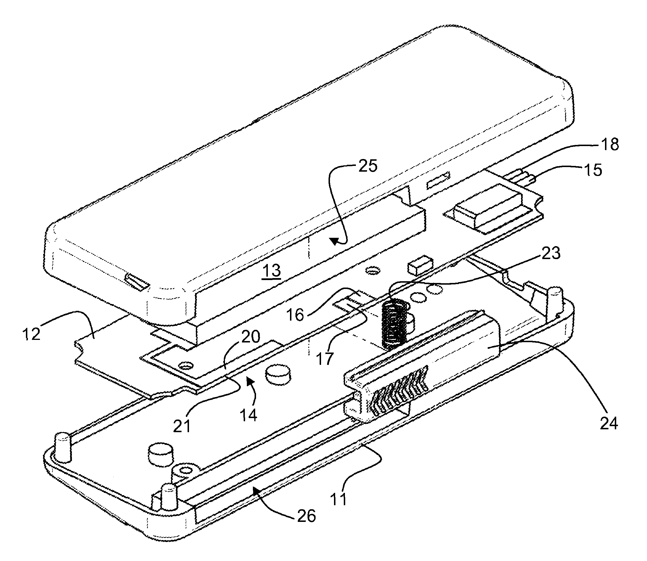
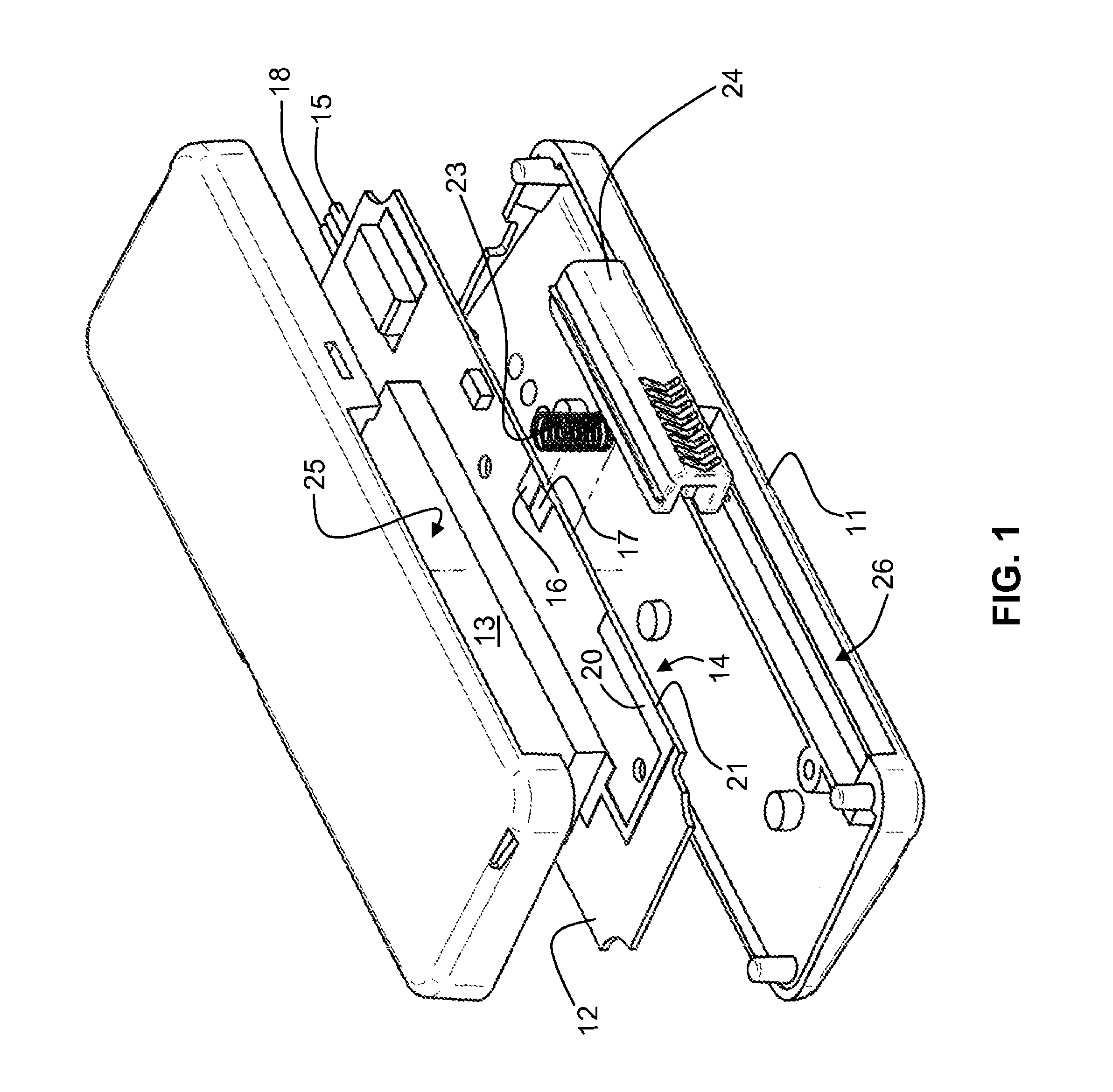
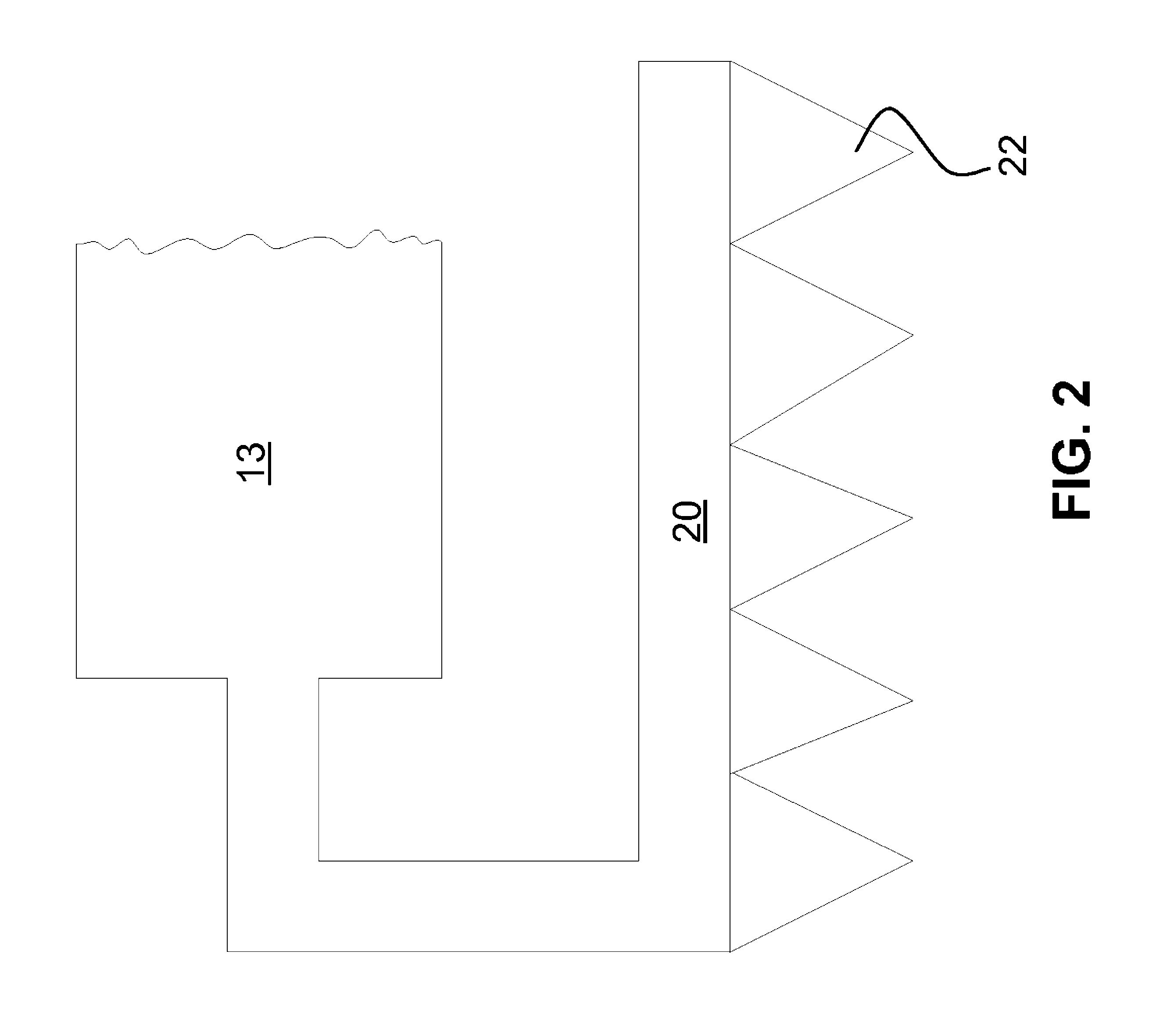
[0028]FIG. 1 shows pictorially an ionizer shown generally as 10 according to an embodiment of the invention comprising a casing 11 in which there is mounted a substrate 12 formed of insulating material supporting an AC high voltage generator 13 an output of which is coupled to an ion emitter shown generally as 14. The AC high voltage generator 13 has a first input (not shown) coupled to a first input power supply terminal 15 and has a second input (not shown) coupled via a pair of planar switch contacts 16 and 17 to a second input power supply terminal 18 disposed on a surface of the substrate 12. The ion emitter 14 is formed as a conductive track 20 on the insulating substrate 13. As shown schematically in FIG. 2, at a front edge 21 of the insulating substrate 13, the conductive track 20 abuts an array of needles 22 that are essentially co-planar with the conductive track 20 and protrude outwardly from the front edge 21 of the insulating substrate 13 by a distance of several micron...


PUM


Abstract

An ionizer includes a high voltage AC generator, and a planar ion emitter mounted on an insulating substrate and having an array of planar needles that protrude from an edge of the substrate. The high voltage AC generator may be actuated by a switch having a pair of mutually insulated planar contacts located near an edge of the insulating substrate and configured to be contacted by an electrically conductive coil spring. The coil spring is supported by a slider that is moveable toward the ion emitter from an initial position wherein the planar contacts are shorted by the spring so as to actuate the high voltage AC generator. Continued movement of the spring collects dust in its coils while breaking the switch contacts and de-energizing the high voltage AC generator.

Description

FIELD OF THE INVENTION[0001]The invention relates to methods and apparatus for bipolar ion generation, of the kind having an AC high voltage source and ion emitter such as are used for destruction of electrostatic charges in industry, as well as domestic appliances of air flow ionization.BACKGROUND OF THE INVENTION[0002]The main condition of efficiency of ion generators is a high ratio of the number of ions leaving the generator to the total number of ions generated by this generator. Realization of this condition largely depends on the ion emitter structure and its position in the generator.[0003]There are such known ion emitters made of a plurality of needles, for example, those described in U.S. Pat. Nos. 4,433,123; 4,498,116; 4,689,715; 4,757,422, 5,837,035 and 6,850,403.[0004]While the advantage of such emitters is their directed ionization from the needle tips, a significant drawback is related to the difficulty to make needles with tips of equal sharpness, which results in un...

Claims


Application Information

Patent Timeline
Patent Type & Authority Patents(United States)
IPC IPC(8): H01J27/00
CPCH01J27/028H01J27/26
Inventor RISKIN, YEFIM Z
Owner FILT AIR
Why Eureka
Try Eureka