Photopolymerization apparatus

a technology of photopolymerization and apparatus, which is applied in the direction of lighting and heating apparatus, process and machine control, instruments, etc., can solve the problems of reducing the efficiency of current devices, increasing energy requirements, and consuming a great deal of power for photocuring devices which utilize a plurality of leds, so as to achieve adequate curing intensity and preserve the life of the diodes.

Inactive Publication Date: 2012-01-31
IPTECH
View PDF6 Cites 11 Cited by
  • Summary
  • Abstract
  • Description
  • Claims
  • Application Information

AI Technical Summary

Benefits of technology

[0008]A light-weight, portable photocuring device delivers light of sufficient intensity to cause photopolymerization using a single light emitting diode (LED). The single high powered LED is driven by a driving circuit controlled by a timing circuit. The driving circuit controls the power applied to the LED insuring sufficient power is applied to the LED to achieve an adequate curing intensity. A heat sink on the LED is monitored by a thermal monitor. The device can be powered with a simple low powered alkaline battery or a high powered lithium ion battery. Only continuous current is supplied to the diode, the LED is not pulsed, therefore the life of the diode is preserved. The single LED can be positioned internally within the device or at the tip of the device. When placed internally, a system of one or more lenses and / or known light focusing means or light guides can be added to the device to further focus and intensify the light provided by the LED.

Problems solved by technology

Photocuring devices which utilize a plurality of LEDs consume a great deal of power and produce much heat.
This increased energy requirement contributes to the weight and complexity of these devices.
Further, complicated systems are needed to capture and focus the light from the multiple LEDs which reduce the efficiency of current devices.

Method used


Image

  • Photopolymerization apparatus
  • Photopolymerization apparatus
  • Photopolymerization apparatus

Examples


Embodiment Construction

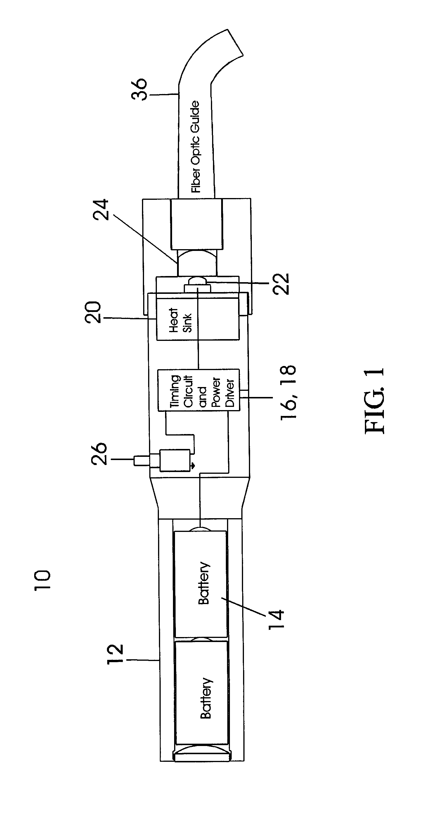
[0017]A preferred embodiment of the apparatus of the subject invention is shown generally at 10 in FIG. 1. FIG. 1 shows a hand-held portable photocuring device that utilizes a single light emitting diode (LED). A housing 12 contains a power supply 14, i.e. batteries, a timing circuit 16, and LED power driver 18, a heat sink 20 and single high power LED 22. The housing can also contain, or be fitted with, a lens system 24 for focusing the light from the LED and a light guide 36. A momentary switch 26 can be placed on the exterior of the housing to activate the timing circuit.

[0018]The power source 14 provides power to a timing circuit and LED power driver. The power source can be one or more alkaline batteries, or rechargeable batteries, such as lithium ion or nickel metal hydride, or the device can be plugged into a wall socket. Batteries allow full maneuverability of the device because it is not restricted by a cord.

[0019]In a preferred embodiment, the timing circuit is an LM 555 t...


PUM


Abstract

A light-weight, portable photocuring device possesses a single multi-wavelength light emitting diode (LED). The single LED backed with a heat sink is driven by a driving circuit and controlled by a timing circuit. A temperature monitor can be included in a closed loop to feed back and control the driver. A multi-plexing device regulates the current to individual ports on the LED effecting the dies allowing the overall wavelength and intensity of the emitted light by the apparatus to be controlled. Lenses and/or light guides in the device act to further direct the light.

Description

CROSS-REFERENCE TO RELATED APPLICATIONS[0001]This application is a continuation-in-part of U.S. patent application Ser. No. 11 / 135,832, filed May 23, 2005, now U.S. Pat. No. 7,535,184 which is a continuation in part of U.S. patent application Ser. No. 10 / 647,028, filed Aug. 22, 2003, now abandoned, which was a continuation of U.S. patent application Ser. No. 09 / 907,140, filed Jul. 17, 2001, now U.S. Pat. No. 6,611,110 B1, which claims the benefits of U.S. Provisional Patent Application No. 60 / 273,105, filed Mar. 2, 2001, and which was a continuation-in-part of U.S. patent application Ser. No. 09 / 765,897 filed Jan. 16, 2001, now U.S. Pat. No. 6,724,156 B2, which claims the benefits of U.S. Provisional Patent Application No. 60 / 176,110, filed Jan. 14, 2000. The disclosure of each of these applications are hereby incorporated by reference in their entirety, including all figures, tables and drawings.STATEMENT REGARDING FEDERALLY SPONSORED RESEARCH OR DEVELOPMENT[0002]Not applicableREFE...

Claims


Application Information

Patent Timeline
Patent Type & Authority Patents(United States)
IPC IPC(8): G05F1/00
CPCA61C19/004H05B33/0803H05B33/0818H05B33/0851H05B33/0887Y10S362/80H05B45/10H05B45/56H05B45/3725
Inventor FREGOSO, GILBERT
Owner IPTECH
Why Eureka
Try Eureka