
Test system

a test system and test method technology, applied in the field of test methods, can solve problems such as input signals, wave reflection, and insufficient transfer of signals, and achieve the effect of preventing or reducing leakage and reducing current consumption

Active Publication Date: 2012-01-31
SAMSUNG ELECTRONICS CO LTD
View PDF13 Cites 4 Cited by
  • Summary
  • Abstract
  • Description
  • Claims
  • Application Information

AI Technical Summary

Benefits of technology

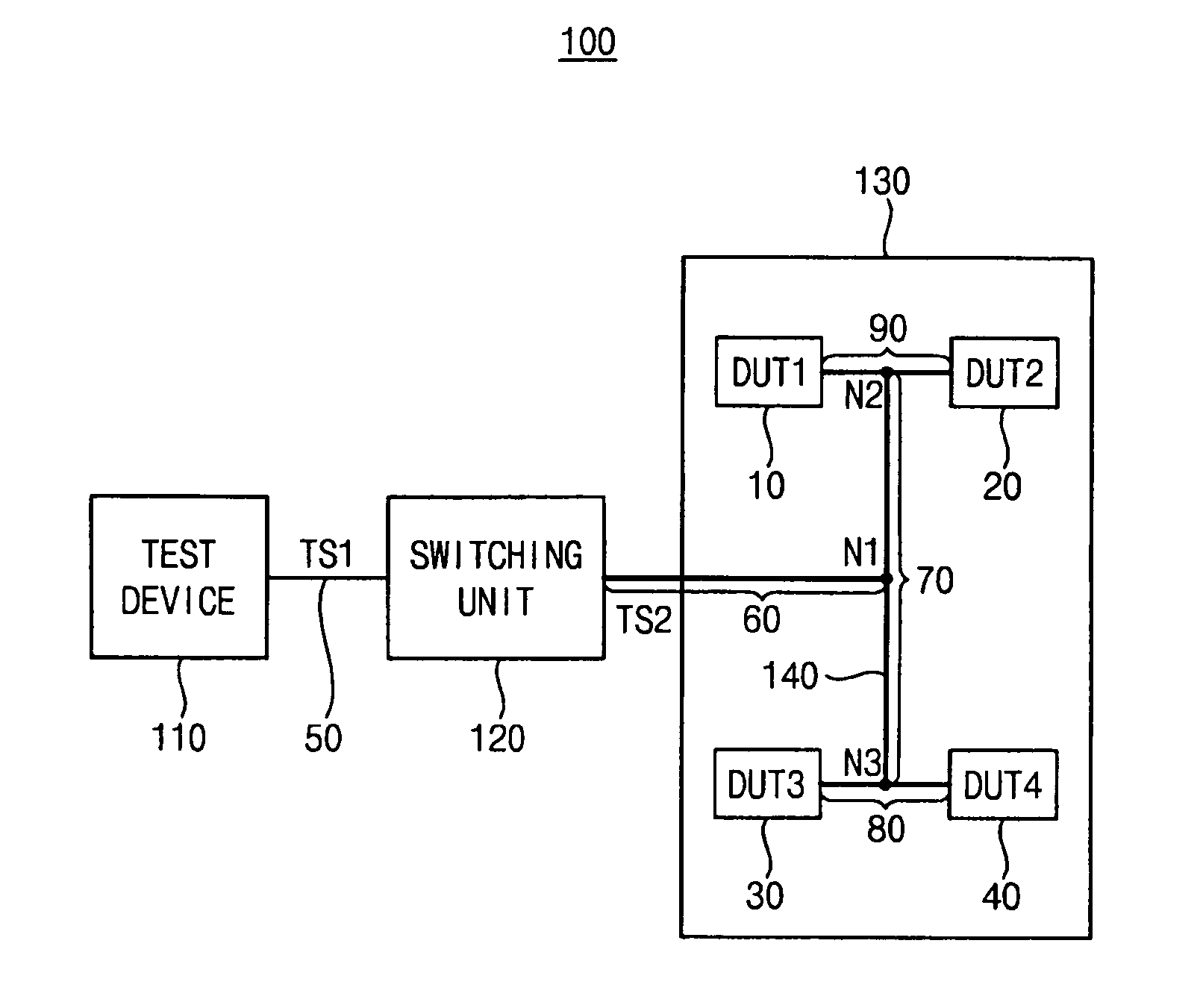
[0007]Example embodiments provide a test system capable of preventing or reducing signal integrity from being degraded, and capable of providing impedance matching.
[0016]In example embodiments, each of the plurality of transmission lines may correspond to a micro-stripe line. Accordingly, reducing current consumption by preventing or reducing leakage according to example embodiments is possible.

Problems solved by technology

In addition, waves are reflected in the branch due to impedance mismatching.
Therefore, input signals, e.g., test patterns, are not properly transferred to the memory devices that operate faster and signal integrity is degraded.
In addition, when a number of layers that are packaged increases causing a gap between the layers, matching impedance is more difficult.

Method used


Image

  • Test system
  • Test system
  • Test system

Examples


Embodiment Construction

[0027]Various example embodiments will be described more fully hereinafter with reference to the accompanying drawings, in which some example embodiments are shown. Example embodiments may, however, be embodied in many different forms and should not be construed as limited to the example embodiments set forth herein. Rather, these example embodiments are provided so that this disclosure will be thorough and complete, and will fully convey the scope of the present invention to those skilled in the art. In the drawings, the sizes and relative sizes of layers and regions may be exaggerated for clarity. Like numerals refer to like elements throughout.

[0028]It will be understood that, although the terms first, second, third etc. may be used herein to describe various elements, these elements should not be limited by these terms. These terms are used to distinguish one element from another. Thus, a first element discussed below could be termed a second element without departing from the t...


PUM


Abstract

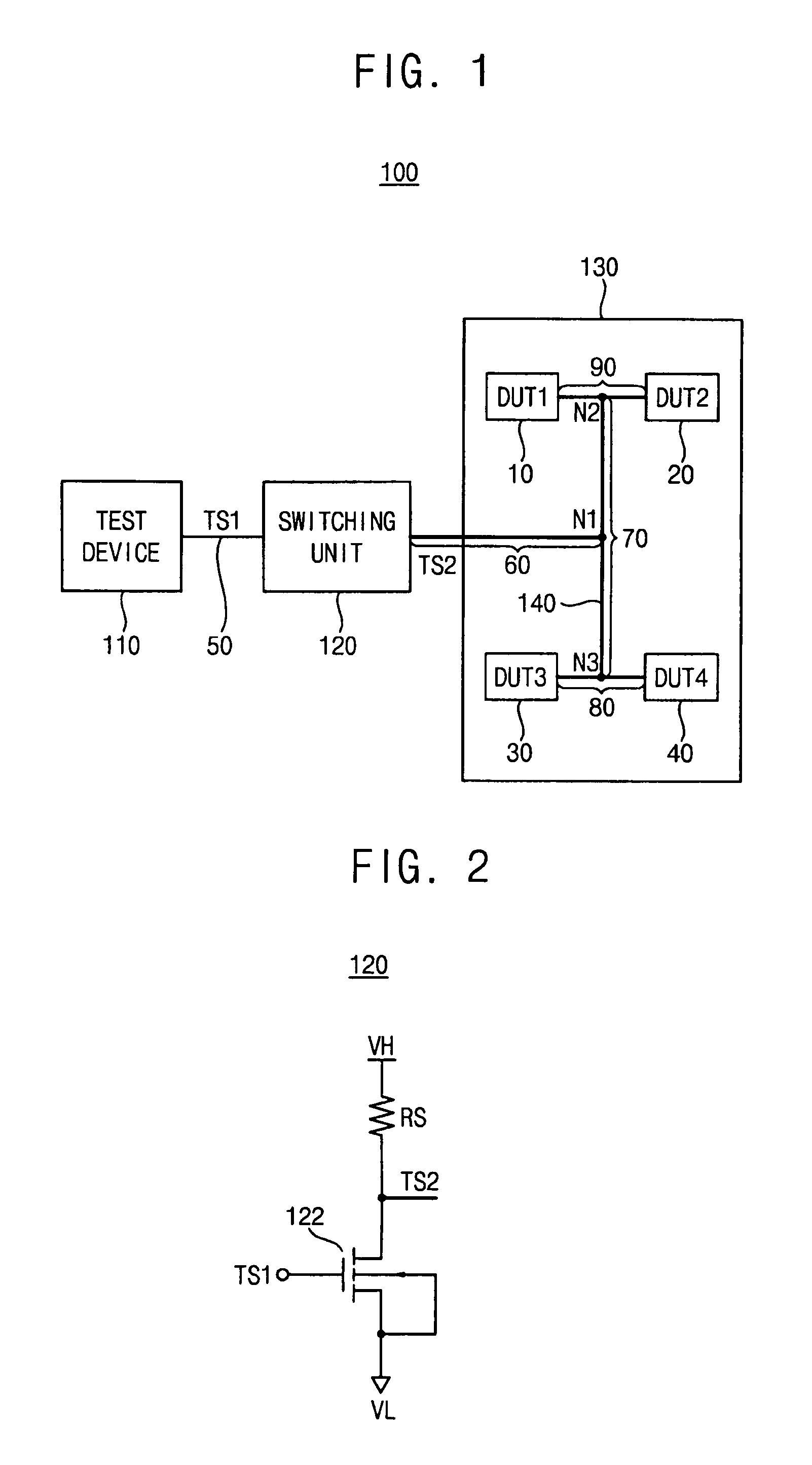
A test system may include a test device, a switching unit and / or a test board. The test device may be configured to generate a first test signal swinging between a first voltage level and a second voltage level, and the first voltage level may be lower than the second voltage level. The switching unit may be coupled to the test device, and configured to switch the first test signal to provide a second test signal swinging between a third voltage level and a fourth voltage level. The third voltage level may be lower than the fourth voltage level. A plurality of devices under test (DUTs) may be mounted on the test board. Each of the plurality of DUTs may be connected in parallel with respect to one another to the switching unit through a transmission line.

Description

PRIORITY STATEMENT[0001]This application claims priority under 35 USC §119 to Korean Patent Application No. 2008-0062440, filed on Jun. 30, 2008, in the Korean Intellectual Property Office (KIPO), the entire contents of which are herein incorporated by reference.BACKGROUND[0002]1. Technical Field[0003]Example embodiments relate to a test system, and more particularly, to a test system that performs a package test.[0004]2. Description of the Related Art[0005]Increasing the operating speed of memories in many applications and manufacturing memory devices that operate faster is widely required. A package test is necessarily performed to evaluate the memory devices that operate faster. The manufacturers test simultaneously many memory devices in order to reduce the cost of the backend process. A test system transfers simultaneously a test pattern to many memory devices on a test board through a branch configuration.[0006]When data is transferred to memory devices that operate slowly thr...

Claims


Application Information

Patent Timeline
Patent Type & Authority Patents(United States)
IPC IPC(8): G01R31/02
CPCG01R31/31926G11C29/56G11C2029/2602G11C2029/5602G01R31/26G01R31/3183H01L22/00
Inventor SONG, KI-JAESEO, HUN-KYO
Owner SAMSUNG ELECTRONICS CO LTD
Learn More