Circuit and method for providing a corrected duty cycle

a technology of duty cycle and circuit, applied in pulse manipulation, pulse duration/width modulation, pulse technique, etc., can solve the problems of time delay, large influence on the performance of ddr sdram, and time delay,

Active Publication Date: 2012-01-31
ELITE SEMICON MEMORY TECH INC
View PDF11 Cites 12 Cited by
  • Summary
  • Abstract
  • Description
  • Claims
  • Application Information

AI Technical Summary

Problems solved by technology

When the external clock signal is input to the synchronous semiconductor memory device, a time delay occurs due to a clock skew between the external clock signal and the internal clock signal.
As the operational speed of the DDR SDRAM is increased, performance of the DDR SDRAM is greatly affected by performance of the DLL.
In addition, variations in process, supply voltage and temperature can affect the driving ability of the circuit, thereby creating timing and / or noise problems and worsening the design margin of the duty cycle.
Therefore, the circuit 100 is complex and requires a large silicon area.

Method used


Image

  • Circuit and method for providing a corrected duty cycle
  • Circuit and method for providing a corrected duty cycle
  • Circuit and method for providing a corrected duty cycle

Examples


Embodiment Construction

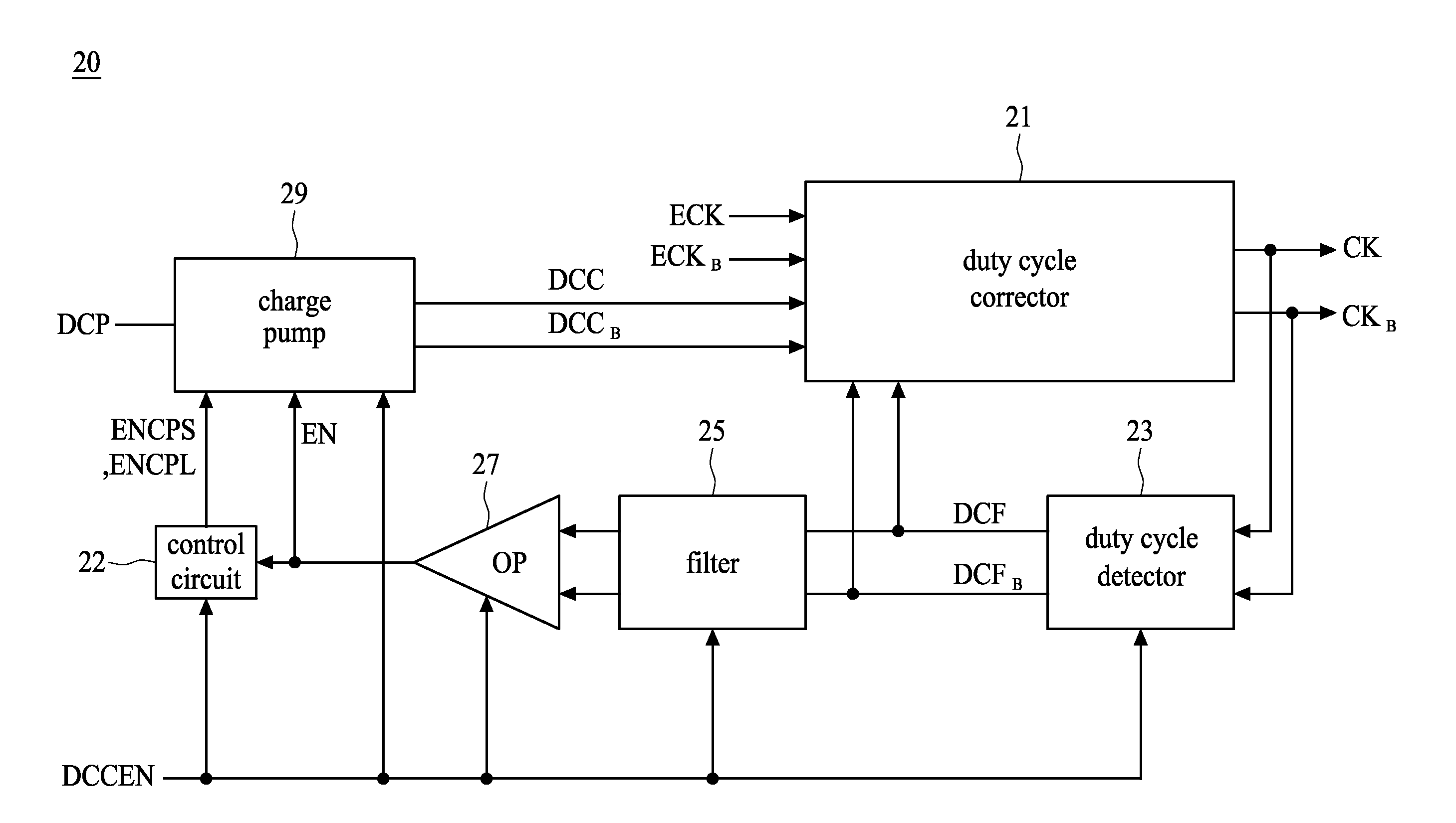
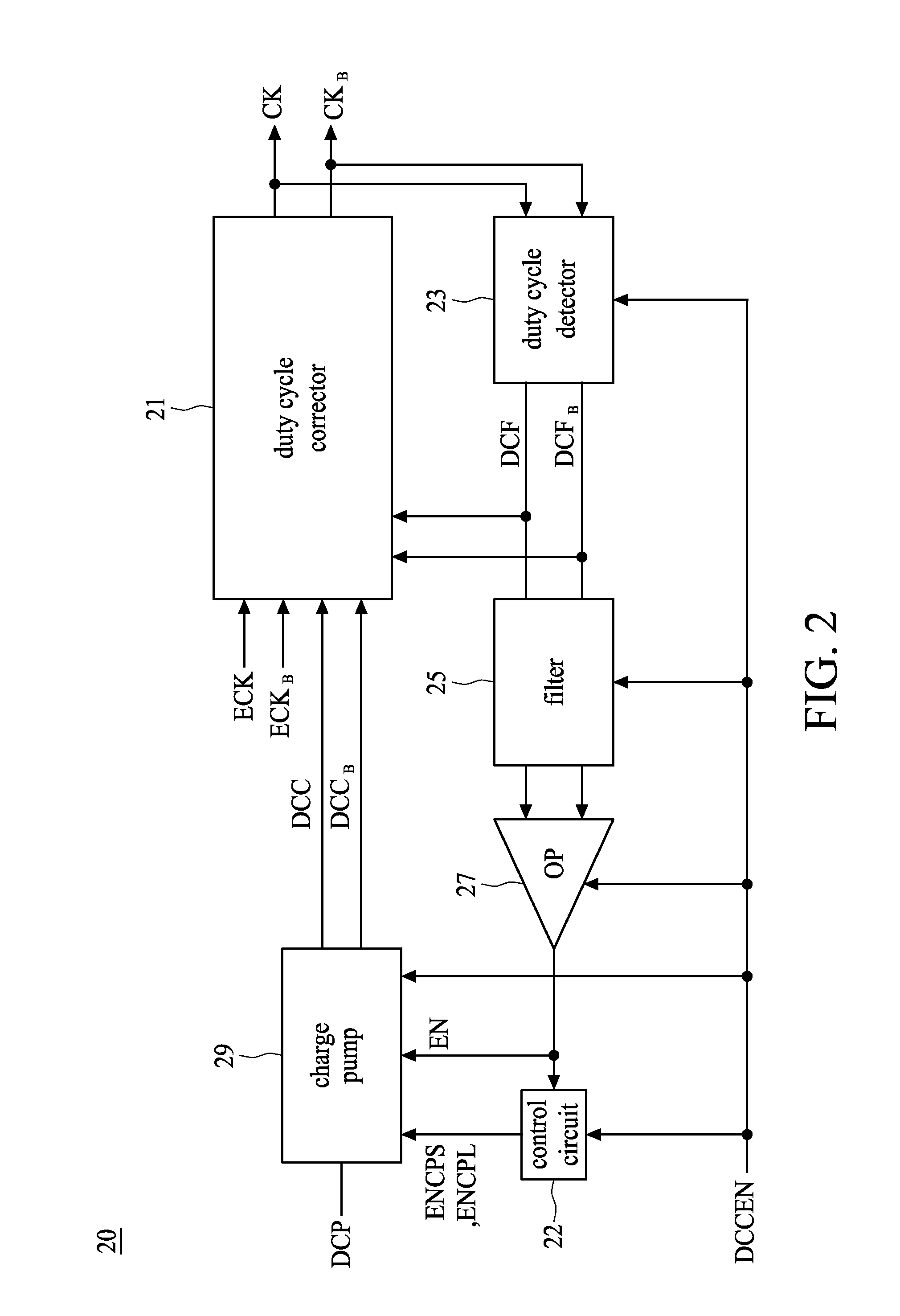
[0023]FIG. 2 shows a block diagram of a duty cycle correction circuit 20 according to one embodiment of the present invention. The duty cycle correction circuit 20 comprises a duty cycle corrector 21, a control circuit 22, a duty cycle detector 23, a filter 25, an operational amplifier (OP) 27, and a charge pump 29. Referring to FIG. 2, the duty cycle corrector 21 is configured to generate an internal clock signal CK and a complementary internal clock signal CKB according to an external clock signal ECK and a complementary external clock signal ECKB, respectively. The duty cycle detector 23 is configured to generate a fine-tuning control signal DCF and a complementary fine-tuning control signal DCFB according to the internal clock signals CK and CKB. The filter 25 is configured to filter the control signals DCF and DCFB for obtaining average voltages. After receiving the average voltages from the filter 25, the operational amplifier 27 generates an enable signal EN, which controls t...


PUM


Abstract

A duty cycle correction circuit comprises a duty cycle detector, a filter, an amplifier, a charge pump, a control circuit, and a duty cycle corrector. The duty cycle detector is configured to generate a first pair of control signals according to a pair of internal clock signals. The filter is configured to obtain average voltages of the first pair of control signals. The amplifier is configured to compare output voltages of the filter for generating an enable signal, and the control circuit is configured to generate a selection signal according to the enable signal. The charge pump is configured to generate a second pair of control signals according to the enable signal and the selection signal, and the duty cycle corrector is configured to receive a pair of external clock signals, the first pair of control signals, and the second pair of control signals for generating the pair of internal clock signals with a corrected duty cycle.

Description

BACKGROUND OF THE INVENTION[0001]1. Field of the Invention[0002]The present invention relates to a circuit and method for providing a corrected duty cycle.[0003]2. Description of the Related Art[0004]Generally, a delay locked loop (DLL) is used in a synchronous semiconductor memory device, such as a double data rate synchronous dynamic random access memory (DDR SDRAM), to perform synchronization between an internal clock signal and an external clock signal of the synchronous semiconductor memory device. When the external clock signal is input to the synchronous semiconductor memory device, a time delay occurs due to a clock skew between the external clock signal and the internal clock signal. Therefore, the DLL is employed in the synchronous semiconductor memory device for generating the internal clock signal by compensating the clock skew.[0005]The DDR SDRAM inputs and / or outputs data at rising and falling edges of the clock signal to increase the transmission speed of data. As the...

Claims


Application Information

Patent Timeline
Patent Type & Authority Patents(United States)
IPC IPC(8): H03K3/017
CPCH03K5/1565
Inventor CHANG, CHIEN YIHUANG, MING CHIEN
Owner ELITE SEMICON MEMORY TECH INC
Why Eureka
Try Eureka