Stacked pre-driver amplifier

a pre-driver amplifier and amplifier technology, applied in the field of amplifiers, can solve the problems of reducing the efficiency of the overall amplifier circuit, significant cost in creating a dc-dc converter, and power loss in the conversion efficiency, so as to reduce or eliminate power waste, improve efficiency, and reduce voltage

Active Publication Date: 2012-01-31
PSEMI CORP
View PDF3 Cites 30 Cited by
  • Summary
  • Abstract
  • Description
  • Claims
  • Application Information

AI Technical Summary

Benefits of technology

[0020]The above described circuits reduce or eliminate power wasted in reducing voltage from Vbat to Vuse, resulting in improved efficiency.

Problems solved by technology

1) DC-DC voltage converters can be used to provide a lower voltage, but power is lost in the conversion efficiency and there is significant cost in creating a DC-DC converter.
2) A resistor divider can be used to reduce the voltage from the battery voltage to the use voltage, but the power dissipated in the resistor divider is wasted as heat, resulting in reduced efficiency of the overall amplifier circuit.
However, the power dissipated in the transistor is also wasted as heat, resulting in reduced efficiency.
Such limitation is due to physical degradation effects known to one skilled in the art of semiconductor device design and may include gate oxide breakdown due to so-called time-dependent dielectric breakdown (TDDB) or so-called hot carrier injection (HCI).
These physical phenomena cause degradation of device performance of the system or even failure of the system.
However, such a possible solution increases power dissipation in the regulator (110).
Such power would be wasted as heat, reducing the overall efficiency of the power amplifier (PA).

Method used


Image

  • Stacked pre-driver amplifier
  • Stacked pre-driver amplifier
  • Stacked pre-driver amplifier

Examples


Embodiment Construction

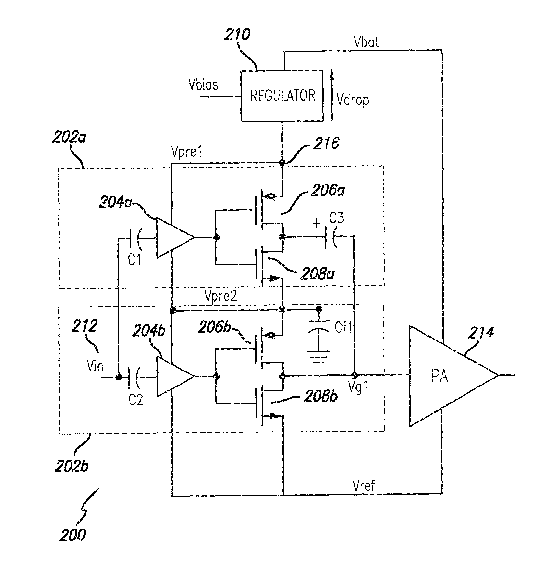
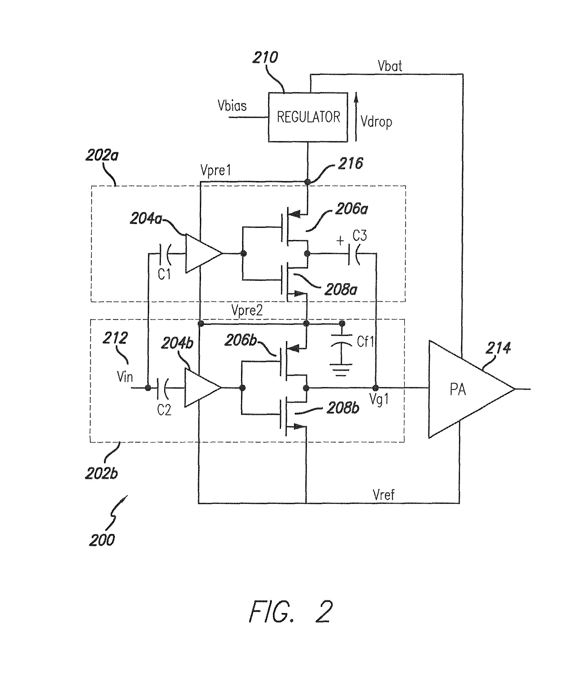
[0026]FIG. 2 shows a block diagram of a power amplifier with a split pre-driver arrangement in accordance with an embodiment of the present disclosure. As shown in FIG. 2, a first pre-driver circuit (202a) is connected to the power supply voltage Vbat in series with a second pre-driver circuit (202b). Therefore, in accordance with this embodiment, the power supply voltage Vbat−Vref is dropped across Vdrop, Vpre1, and Vpre2. In particular, Vbat−Vref=(Vbat−Vpre1)+(Vpre1−Vpre2)+(Vpre2−Vref). By way of example and not of limitation, Vref can be assumed to be equal to electrical ground and Vdrop of regulator (210) is assumed to be equal to zero. In such exemplary embodiment, it follows that Vpre1=Vbat.

[0027]An external source signal Vin (212) is, for example, a RF signal that is capacitively coupled to pre-driver amplifiers (204a) and (204b). In the embodiment of FIG. 2, pre-driver amplifiers (204a) and (204b) amplify the signal Vin (212) without inverting it. Therefore, when Vin (212) i...


PUM


Abstract

A stacked pre-driver stage and a power amplifier including the stacked pre-driver stage are described. The stacked pre-driver stage comprises stacked pre-drivers arranged in series between a supply voltage and a reference voltage. Each pre-driver includes a pre-driving amplifier, together with MOS transistors. Each pre-driver is subject, in operation, to a voltage difference which is inferior to a maximum allowed use voltage of the MOS transistors with a largely reduced voltage drop across the regulator included in the power amplifier.

Description

BACKGROUND[0001]1. Field[0002]The present disclosure relates to amplifiers. More specifically, it relates to a stacked pre-driver amplifier and to devices using a stacked pre-driver amplifier, such as power amplifiers having a stacked pre-driver amplifier.[0003]2. Description of Related Art[0004]Radio frequency power amplifiers are commonly used in many applications. Often, they are used in consumer battery-powered applications such as mobile telephones, for which power efficiency is a very important attribute.[0005]As semiconductor processes shrink to smaller dimensions in order to achieve increased performance, reliability criteria cause a reduction in the maximum allowed voltage across the terminals of a transistor. This maximum allowed voltage is defined as Vuse. Common battery voltages can exceed 3.5V, while maximum transistor voltages may be 2.5V or even less. The voltage imposed on a pre-driver stage of a power amplifier must be reduced from the battery voltage down to Vuse. ...

Claims


Application Information

Patent Timeline
Patent Type & Authority Patents(United States)
IPC IPC(8): H03F3/68
CPCH03F1/0216H03F1/0261H03F3/211H03F3/245H03F3/3028H03F3/423H03F2200/408H03F2200/451H03F2203/21106H03F2203/21142
Inventor ADAMSKI, JAROSLAW EDWARDSHARMA, VIKASNOBBE, DAN WILLIAM
Owner PSEMI CORP
Why Eureka
Try Eureka