
Impulse-type driving method and circuit for liquid crystal display

a liquid crystal display and driving method technology, applied in the direction of electric digital data processing, instruments, computing, etc., can solve the problems of not being able to drive in the only feasible way, fuzzy dynamic images, etc., and achieve the effect of low cost, low power consumption, and increased data transmission amount of the system

Active Publication Date: 2012-02-07
NOVATEK MICROELECTRONICS CORP
View PDF7 Cites 2 Cited by
  • Summary
  • Abstract
  • Description
  • Claims
  • Application Information

AI Technical Summary

Benefits of technology

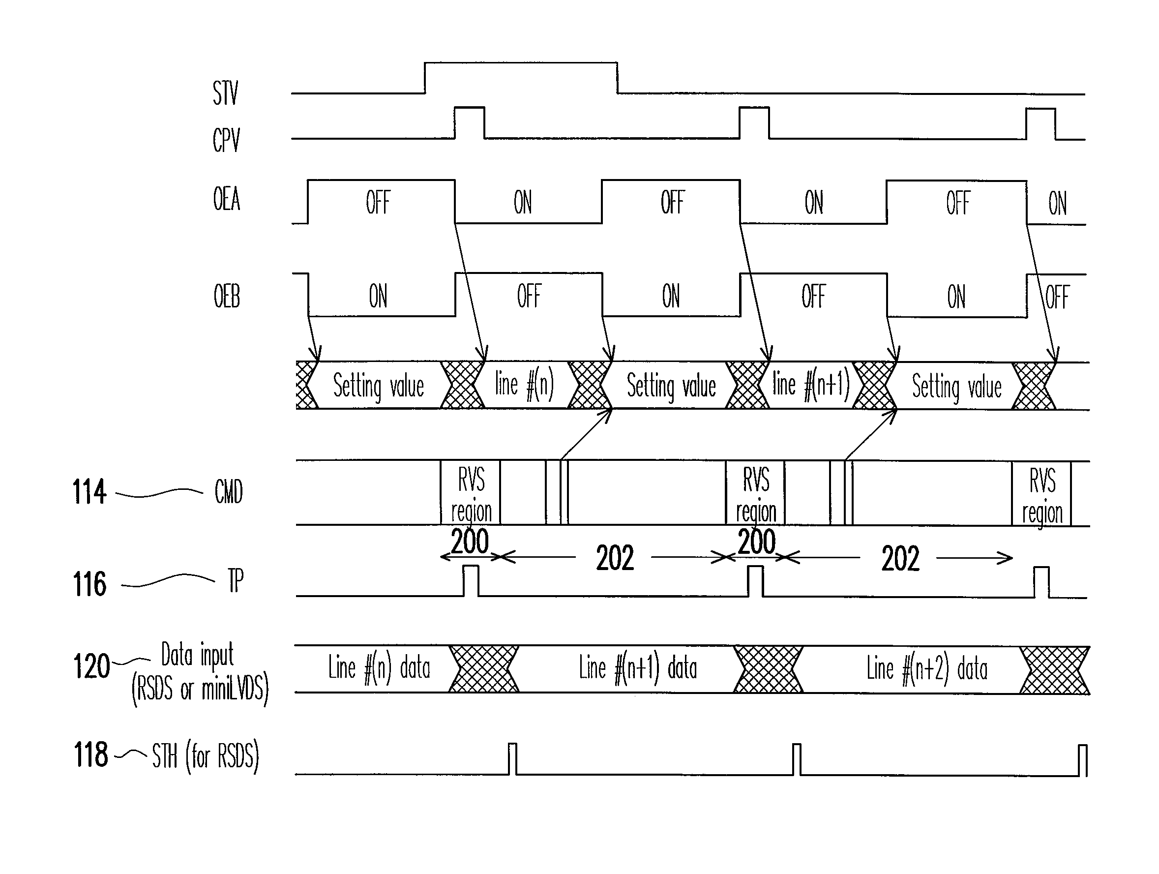
The present invention provides an impulse-type driving method and circuit architecture for a source driver and timing controller of an LCD. The method includes providing a set of impulse control signals to the source driver, which includes a command signal with a field of determining data voltage polarity and a command field. The command field allows for adding a dynamic command in accordance with a desired action. The method also includes providing an output enable signal to a gate driver and a vertical synchronous signal for controlling the timing of the output enable signal. The invention provides a new system interface protocol for LCDs, which allows for low-cost and low-power consumption. The invention also provides a driving circuit with a timing controller that includes a receiving interface unit for receiving and decoding an input data to obtain a data clock, and a command circuit unit for generating the command signal based on the data clock. The invention also includes a command detector for receiving the data clock and generating the command enable signal. The technical effects of the invention include improved driving efficiency, reduced power consumption, and improved display brightness adjustment.

Problems solved by technology

Whenever a pixel voltage is written, a frame period is kept, but this display mode may lead to fuzzy dynamic images.
However, in accordance with different driving mechanisms, the above driving manner is not the only feasible way.

Method used


Image

  • Impulse-type driving method and circuit for liquid crystal display
  • Impulse-type driving method and circuit for liquid crystal display
  • Impulse-type driving method and circuit for liquid crystal display

Examples


Embodiment Construction

[0047]Reference will now be made in detail to the present embodiments of the invention, examples of which are illustrated in the accompanying drawings. Wherever possible, the same reference numbers are used in the drawings and the description to refer to the same or like parts.

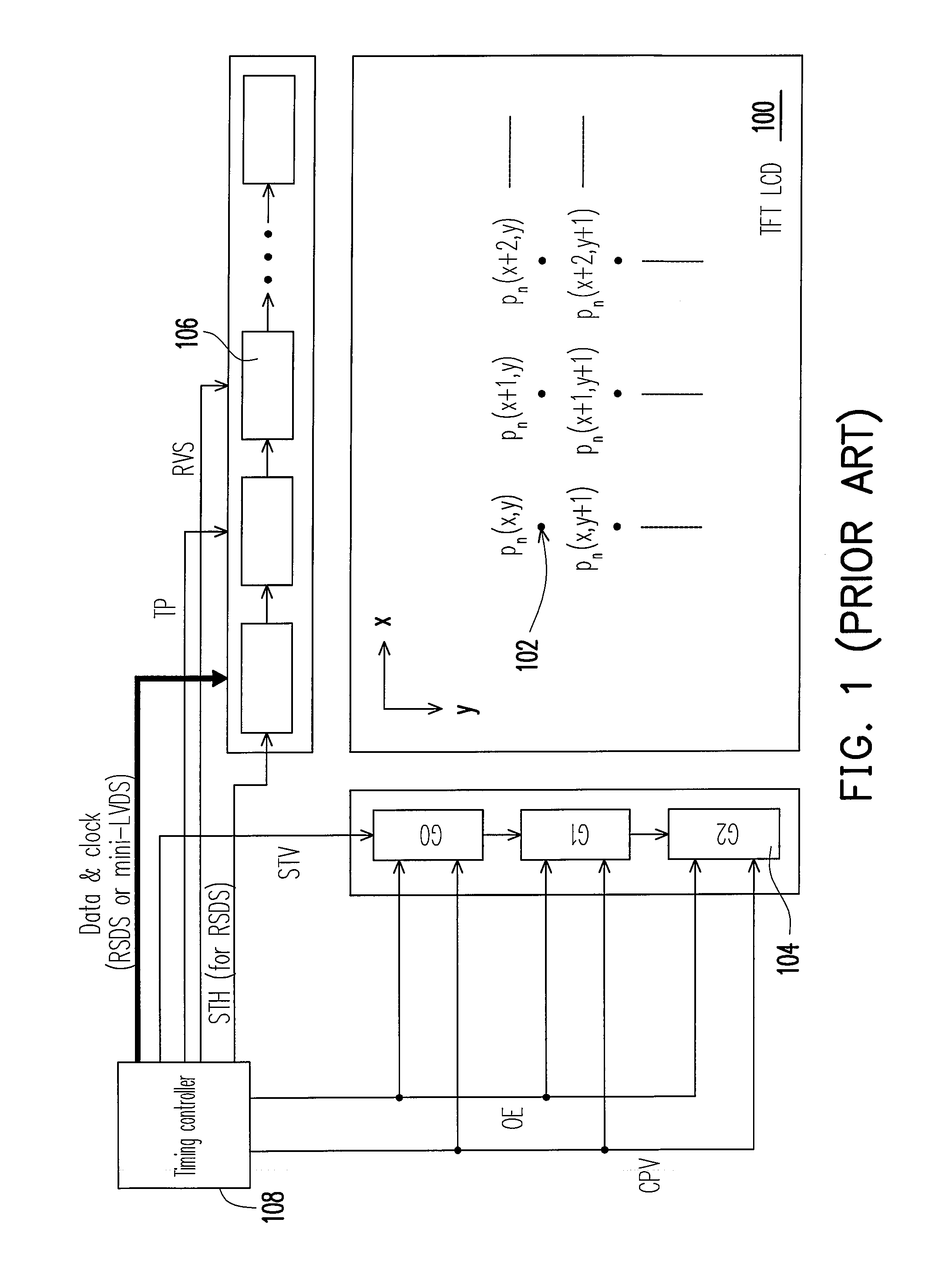
[0048]The present invention provides an impulse-type driving method and a circuit architecture of a source driver and a timing generator. In addition, the present invention also provides a new system interface protocol, for example, a hardware architecture with low cost and low power consumption, but capable of implementing impulse-type driving without substantially raising the data transmission amount of the system. Embodiments are given below for illustrating the present invention, and the present invention is not limited thereto.

[0049]FIG. 3 is a schematic view of a signal time sequence of an impulse-type driving method for an LCD according to an embodiment of the present invention. Referring to FIG. 3, a s...


PUM


Abstract

An impulse-type driving method for a liquid crystal display (LCD) is used for driving a pixel array of an LCD panel. The method includes providing a set of impulse control signals to a source driver. The source driver, according to the set of impulse control signals, drives the pixel array. The set of impulse control signals includes a command signal. The command signal includes a field of determining data voltage polarity and a command field. According to a time sequence, the field of determining data voltage polarity provides a polarity data for determining a voltage polarity output by the source driver. The command field and the field of determining data voltage polarity are consecutively and alternatively output, in which the command field allows to add a dynamic command in accordance with a desired action.

Description

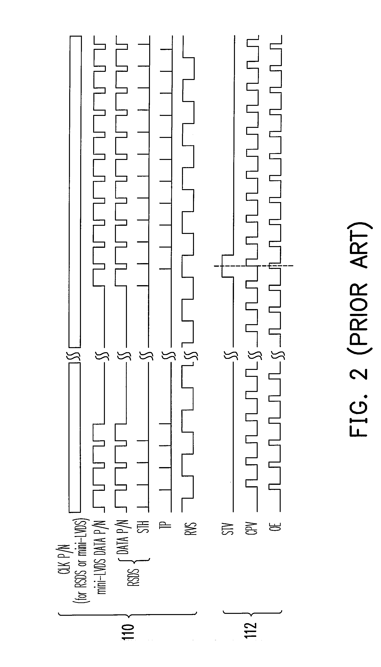
CROSS-REFERENCE TO RELATED APPLICATION[0001]This application claims the priority benefit of Taiwan application serial no. 97103281, filed on Jan. 29, 2008. The entirety the above-mentioned patent application is hereby incorporated by reference herein and made a part of specification.BACKGROUND OF THE INVENTION[0002]1. Field of the Invention[0003]The present invention generally relates to a driving technique for a liquid crystal display (LCD), in particular, to a source driving and gate driving technique.[0004]2. Description of Related Art[0005]LCDs, especially thin film transistor (TFT) LCDs, have been widely utilized. Images on an LCD are displayed by a pixel array formed of a plurality of pixels, and each pixel displays a corresponding colour according to a time sequence of a frame. In order to drive the pixel display, various control signals are required, and usually a gate driver and a source driver are used to perform intersection control.[0006]The conventional TFT LCD adopts a...

Claims


Application Information

Patent Timeline
Patent Type & Authority Patents(United States)
IPC IPC(8): G06F3/038
CPCG09G3/2011G09G3/2096G09G5/008G09G3/3614G09G3/3688G09G2320/0252
Inventor HU, YU-TSUNG
Owner NOVATEK MICROELECTRONICS CORP
Learn More