Disk drive flexure

a technology of flexure and disk drives, applied in the field of flexure, can solve problems such as increasing the number of components, and achieve the effect of excellent electrical properties

Active Publication Date: 2012-02-07
NHK SPRING CO LTD
View PDF9 Cites 30 Cited by
  • Summary
  • Abstract
  • Description
  • Claims
  • Application Information

AI Technical Summary

Benefits of technology

[0014]The present invention provides a disk drive flexure having excellent electrical properties, such as low high-frequency attenuation, and configured so that an interleave circuit can be prevented from becoming thick.
[0019]According to this arrangement, the first and second jumper conductors that are flush with the metal base are angled at 45° or less to the axis which extends in the wiring direction of each interleaved conductor. Thus, the high-frequency attenuation can be reduced, and an interleave circuit suitable for high-speed data transfer can be obtained.

Problems solved by technology

Since the connecting wires 230 and 231 are required in addition to the interleaved conductors 201 to 204, moreover, there is also a problem of an increase in the number of components.

Method used


Image

  • Disk drive flexure
  • Disk drive flexure
  • Disk drive flexure

Examples


Embodiment Construction

[0043]A first embodiment of the present invention will now be described with reference to FIGS. 1 to 9.

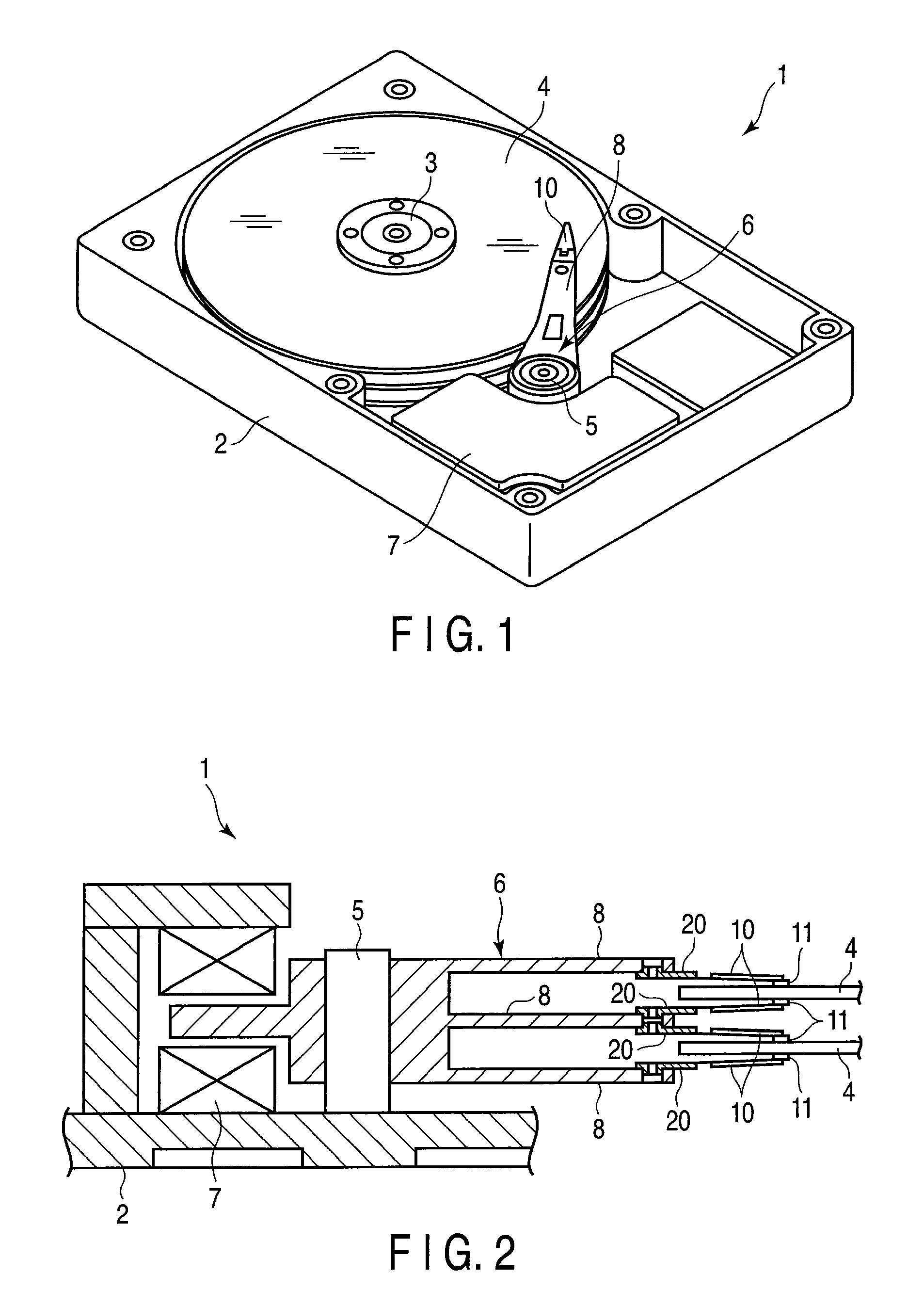
[0044]A hard disk drive (hereinafter referred to as a “disk drive”) 1 shown in FIG. 1 comprises a case 2, magnetic disks 4, carriage 6, and positioning motor 7. The magnetic disks 4 are rotatable about a spindle 3. The carriage 6 is turnable about a pivot 5. The positioning motor 7 turns the carriage 6. The case 2 is covered by a lid (not shown).

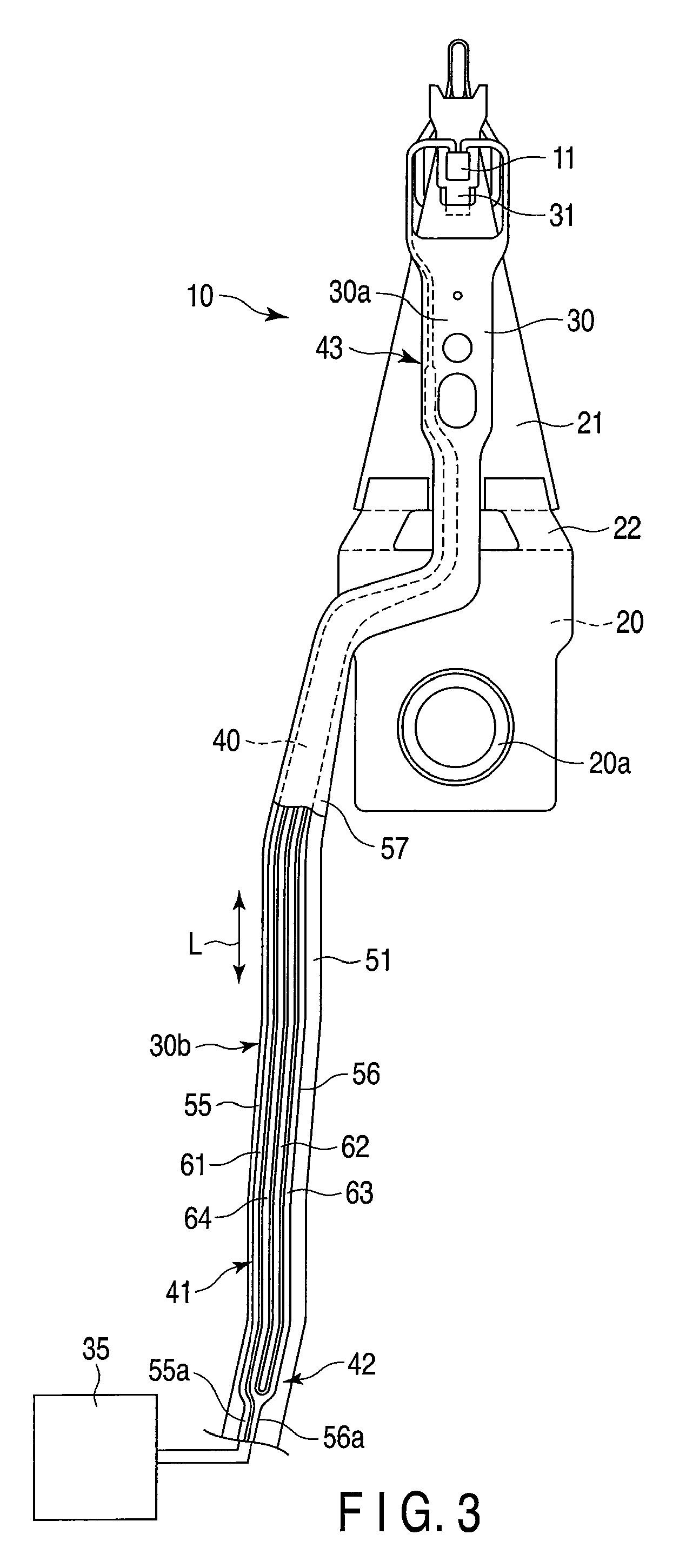
[0045]FIG. 2 is a sectional view typically showing a part of the disk drive 1. As shown in FIG. 2, the carriage 6 comprises a plurality of (e.g., three) actuator arms 8. Suspensions 10 are mounted individually on the respective distal end portions of the actuator arms 8. A slider 11, which constitutes a magnetic head, is disposed on the distal end of each of the suspensions 10.

[0046]If the magnetic disks 4 rotate at high speed about the spindle 3, an air bearing is formed between each disk 4 and slider 11. If the carriage 6 is moved by the ...


PUM

PropertyMeasurementUnit
anglesaaaaaaaaaa
thickaaaaaaaaaa
thickaaaaaaaaaa

Abstract

A first conductor member includes an amplifier-side first conductor, a head-side first conductor, and first and second interleaved conductors. A second conductor member includes an amplifier-side second conductor, a head-side second conductor, and third and fourth interleave conductors. The second interleaved conductor is connected to the amplifier-side first conductor through a first jumper conductor. The fourth interleave conductor is connected to the head-side second conductor through a second jumper conductor. The jumper conductors are formed by partially etching a metal base. The jumper conductors are individually inclined at angles of 45° or less to an axis which extends in a wiring direction of each of the interleaved conductors.

Description

CROSS-REFERENCE TO RELATED APPLICATIONS[0001]This application is based upon and claims the benefit of priority from prior Japanese Patent Application No. 2009-118631, filed May 15, 2009, the entire contents of which are incorporated herein by reference.BACKGROUND OF THE INVENTION[0002]1. Field of the Invention[0003]This invention relates to a flexure used in a disk drive for an information processing apparatus, such as a personal computer.[0004]2. Description of the Related Art[0005]A hard disk drive (HDD) is used in an information processing apparatus, such as a personal computer. The hard disk drive comprises a magnetic disk rotatable about a spindle, carriage turnable about a pivot, etc. A disk drive suspension is disposed on an arm of the carriage.[0006]The disk drive suspension comprises a baseplate and load beam. A flexure is located on the load beam. A slider is mounted on a gimbal portion formed near the distal end of the flexure. The slider is provided with elements (transd...

Claims


Application Information

Patent Timeline
Patent Type & Authority Patents(United States)
IPC IPC(8): G11B21/16
CPCG11B5/4833G11B5/484
Inventor ARAI, HAJIME
Owner NHK SPRING CO LTD
Why Eureka
Try Eureka