Sequential valve member driving mechanism for an HVAC system

a technology of hvac system and driving mechanism, which is applied in the direction of valve operating means/release devices, transportation and packaging, and light and heating apparatus, etc. it can solve the problems of limiting the compactness of the entire hvac system, unable to achieve linearity of air mixing doors, and less adept at attaining. achieve the desired comfort level for passengers and improve the packaging characteristics of the hvac system

Inactive Publication Date: 2012-02-14
MAHLE INT GMBH
View PDF23 Cites 16 Cited by
  • Summary
  • Abstract
  • Description
  • Claims
  • Application Information

AI Technical Summary

Benefits of technology

[0012]An advantage of the present invention is to provide a driving mechanism for sliding first and second valve plates, which improves packaging characteristics of the HVAC system.
[0013]Another advantage of the present invention is to provide a driving mechanism that improves mixing of cold and hot air streams to achieve a desired temperature to control air flow into the interior of the automotive vehicle by sliding the first and second valve plates between the first and second positions to achieve a desired comfort level for a passenger.
[0014]Still another advantage of the present invention is to provide a driving mechanism that eliminates the need for baffles or mixing doors used in the prior art patents for mixing of cold and hot air streams to achieve a desired temperature in the interior of the automotive vehicle.

Problems solved by technology

Such systems obviously require enough space between the evaporator and the heater for air mixing doors, positioned therebetween, to swing, limiting how compact the entire HVAC system can be made.
In addition, the air mixing doors tend to lack linearity.
That is, they tend to be all on, or all off, but are far less adept at attaining.
The first and second mixing doors are substantially spaced from one another thereby diminishing packaging value of the air conditioning system.
Unfortunately, the door mechanism taught by the U.S. Pat. No. 6,305,462 to Tsurushima et al. separates cold and hot air streams therefore without promoting mixing of the cold and hot air streams, which results in the need for various baffles and / or a mixing door to be added to achieve a desired temperature.

Method used


Image

  • Sequential valve member driving mechanism for an HVAC system
  • Sequential valve member driving mechanism for an HVAC system
  • Sequential valve member driving mechanism for an HVAC system

Examples


Embodiment Construction

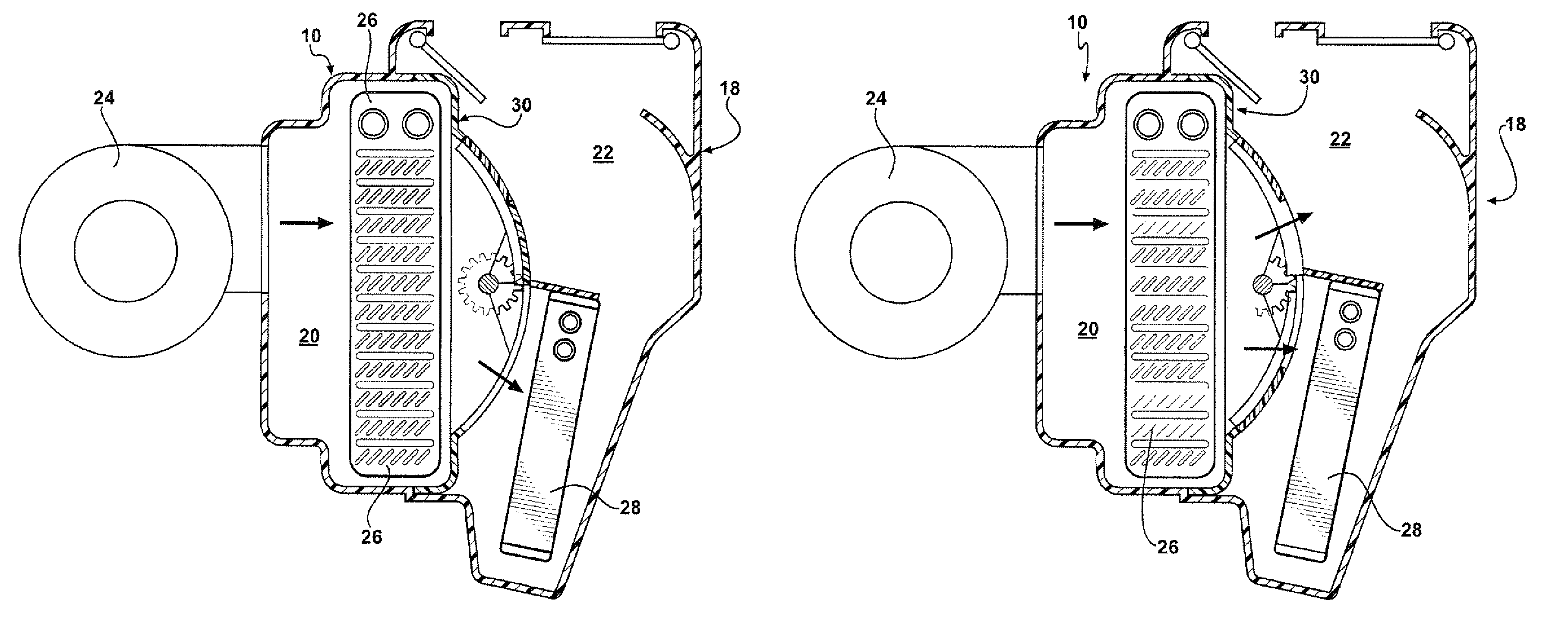
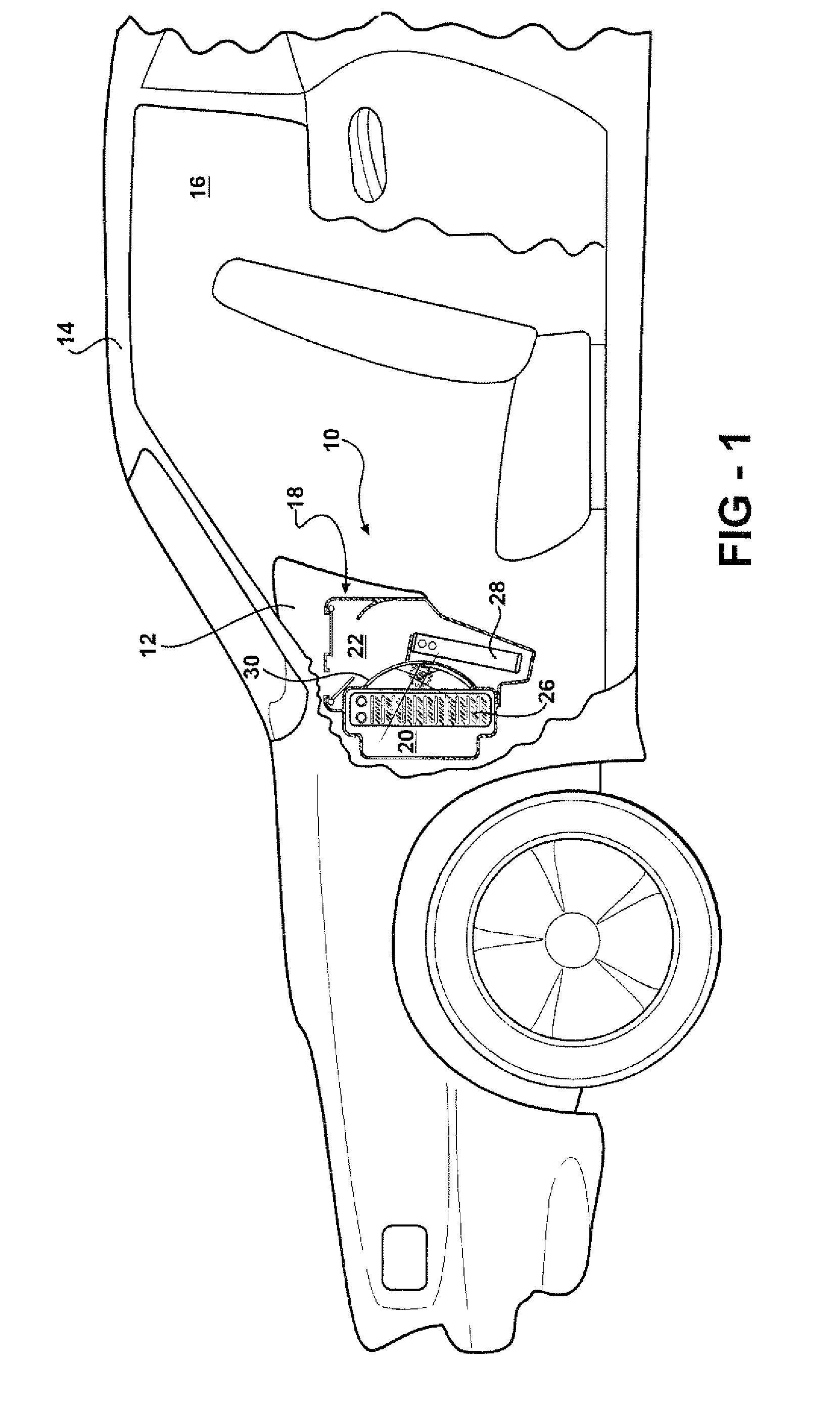
[0027]Referring to FIGS. 1, 6, 8, and 10, an air conditioning system 10, generally shown, is disposed in an instrument panel 12 on the front side of a passenger compartment 16 of a vehicle 14. The air conditioning system 10 includes a housing 18, generally indicated, having at least two air passages 22 or sections 20 disposed in side by side relationship. A blower device 24 is connected to the housing 18 for introducing air therein. An evaporator 26 is disposed in one of the sections 20 of the housing 18 for taking heat from the air discharged from the blower device 24 to produce cool air. A heater 28 is disposed in the other of the sections 20 and is positioned downstream of the evaporator 26 for adding heat to the cool air to produce warm air.

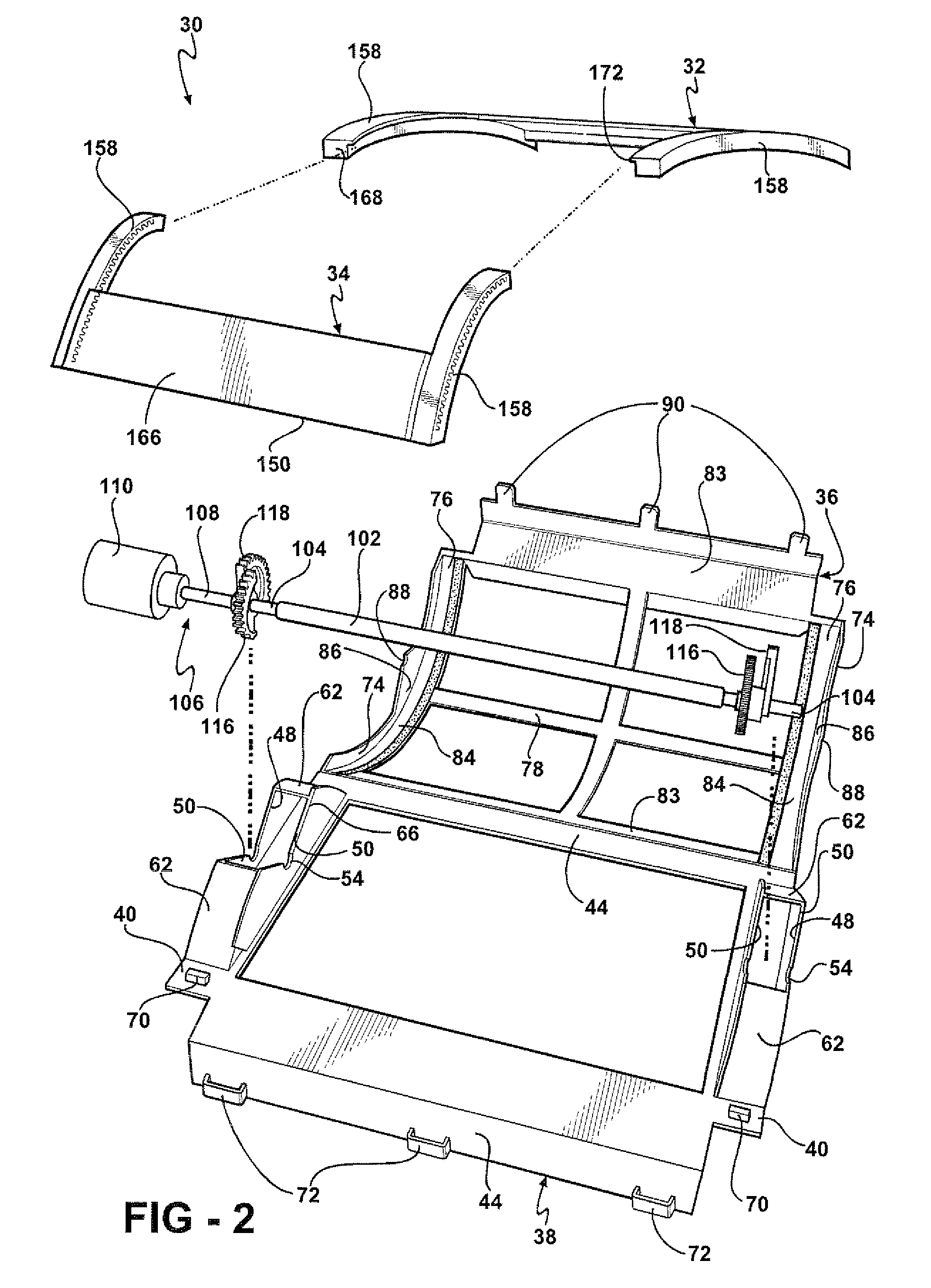
[0028]As illustrated in FIG. 2, a support frame 30, generally shown, of the air conditioning system 10 is designed for holding a first sliding valve plate 32 and a second sliding valve plate 34, discussed in greater details further below. The...


PUM


Abstract

An air conditioning system of the present invention for an automotive vehicle includes a housing having at least two sections connected by two side by side air passage. A blower device of the air conditioning system discharges air into the housing. An evaporator is disposed in one of the sections for taking heat from the air discharged from the blower device to produce cool air. A heater is disposed in the other section positioned downstream of the evaporator for adding heat to the cool air to produce warm air. First and second sliding valve plates mechanically communicating with a driving mechanism of the present invention are supported by the housing for selectively closing the two side by side air passages thereby regulating air flow of cool and warm air.

Description

CROSS REFERENCE TO RELATED APPLICATION[0001]This application claims the benefit of a provisional application Ser. No. 60 / 605,053 filed on Aug. 27, 2004 and is a continuation in part of application Ser. No. 11 / 115,567 filed on Apr. 27, 2005.BACKGROUND OF THE INVENTION[0002]1. Field of the Invention[0003]The subject invention relates to an automotive heating ventilation and air conditioning (HVAC) systems of the type, and more particularly to a door mechanism of the HVAC system, which can slide therein to control air flow.[0004]2. Description of the Prior Art[0005]Modern vehicles are designed to provide passengers with comfort, convenience, and safety. One comfort system that few could live without is an air conditioning system. The air conditioning system is used in the modern vehicles is designed to cool, dehumidify, clean, and circulate the air in a vehicle. The air conditioning system presents a closed, pressurized system that has a compressor, a condenser, a receiver / dehydrator (...

Claims


Application Information

Patent Timeline
Patent Type & Authority Patents(United States)
IPC IPC(8): B60H1/00
CPCB60H1/00692B60H1/00835Y10T137/86928Y10T137/87732Y10T137/87772Y10T137/86847
Inventor STEVENSON, MARK W.
Owner MAHLE INT GMBH
Why Eureka
Try Eureka