Chain conveyor having damping device

a technology of damping device and chain conveyor, which is applied in the direction of control device of conveyor, conveyor parts, transportation and packaging, etc., can solve the problems of damping device, reducing the speed difference between the conveying section and the return section, and damping the vibration of the conveying means, so as to reduce the damping effect of the damping device, prevent play, and dampen vibration

Inactive Publication Date: 2012-02-14
ROBERT BOSCH GMBH
View PDF18 Cites 8 Cited by
  • Summary
  • Abstract
  • Description
  • Claims
  • Application Information

AI Technical Summary

Benefits of technology

[0011]In the case of a preferred conveyor, the damping device includes a spring, via which it is supported on the frame. Using the spring, a preload force can be impressed in the damping device, thereby eliminating any play that may be present between the conveying means and the driving wheel. Play of that type would greatly reduce the damping effect of the damping device. It is not necessary to provide friction-producing means in the proposed damping device since the friction between the conveying means and the frame is used to dampen vibrations. It is entirely adequate for the driving wheel, according to the invention, to be movably coupled to the conveying section and the return section without play in every operating state, which is achieved using the spring that is provided.
[0012]In the case of a preferred conveyor, the spring is supported on the frame using a displaceable stop. The endless conveying means becomes worn over time by the operation of the conveyor. In the case of conveying means designed as a conveying chain in particular, this wear causes the conveying means to gradually lengthen. This gradual lengthening can be compensated for by the displaceable stop, thereby preventing play from occurring between the driving wheel and the conveying means even if the conveying means become worn.
[0013]In the case of a preferred conveyor, the rotary axle of the driving wheel is supported on the frame using a linear guide such that it can move in a translatory manner, wherein the guidance direction of the linear guide extends substantially parallel to the adjacent region of the conveying section. A sliding guide is used particularly preferably as the linear guide. The orientation of the linear guide, which is provided, substantially matches the direction of vibration of the rotating conveying means, and so the damping device is as effective as possible. In addition, the support that is provided is so space-saving that it can be easily disposed between the conveying section and the return section of the conveying means.
[0014]In the case of another preferred conveyor, a lever arm is provided that is supported at a first end in a rotational manner on the frame, wherein the driving wheel is rotatably accommodated on a second end that is opposite the first end, the damping device damping the rotational motion of the lever arm. Although a lever arm requires more space than the linear guide described above, it is much less expensive to manufacture. In addition, only pivot bearings are required, which are available as cost-effective, low-wear standard parts e.g. in the form of radial deep-groove ball bearings. It should be noted that the length and orientation of the lever should be selected such that the rotary axle of the driving wheel moves at least approximately parallel to the adjacent region.
[0015]In the case of a preferred conveyor, the driving wheel is disposed adjacent to a drive of the endless conveying means. The effects of stick-slip vibration in the form of speed differences between the conveying section and the return section of the conveying means are often the greatest in the vicinity of the drive, and so this is where the damping has the greatest effect. At the same time, the drive is stressed particularly greatly by the aforementioned vibrations, and so the proposed placement of the driving wheel reduces the stress on the drive and thereby increases its service life. In the case of a preferred conveyor, the endless conveying means is designed in the form of a chain having a large number of separate chain links, each chain link including a transport plate; the transport plates define the conveying surface. A conveyor of that type is known from U.S. Pat. No. 4,961,492 A. The invention is particularly advantageous for a conveyor of that type because that is where stick-slip vibrations are particularly strong, and because that is where a particularly space-saving damping device is required.

Problems solved by technology

The damping device reduces the difference in speed between the conveying section and the return section, thereby damping the vibration of the conveying means.

Method used


Image

  • Chain conveyor having damping device
  • Chain conveyor having damping device

Examples


Embodiment Construction

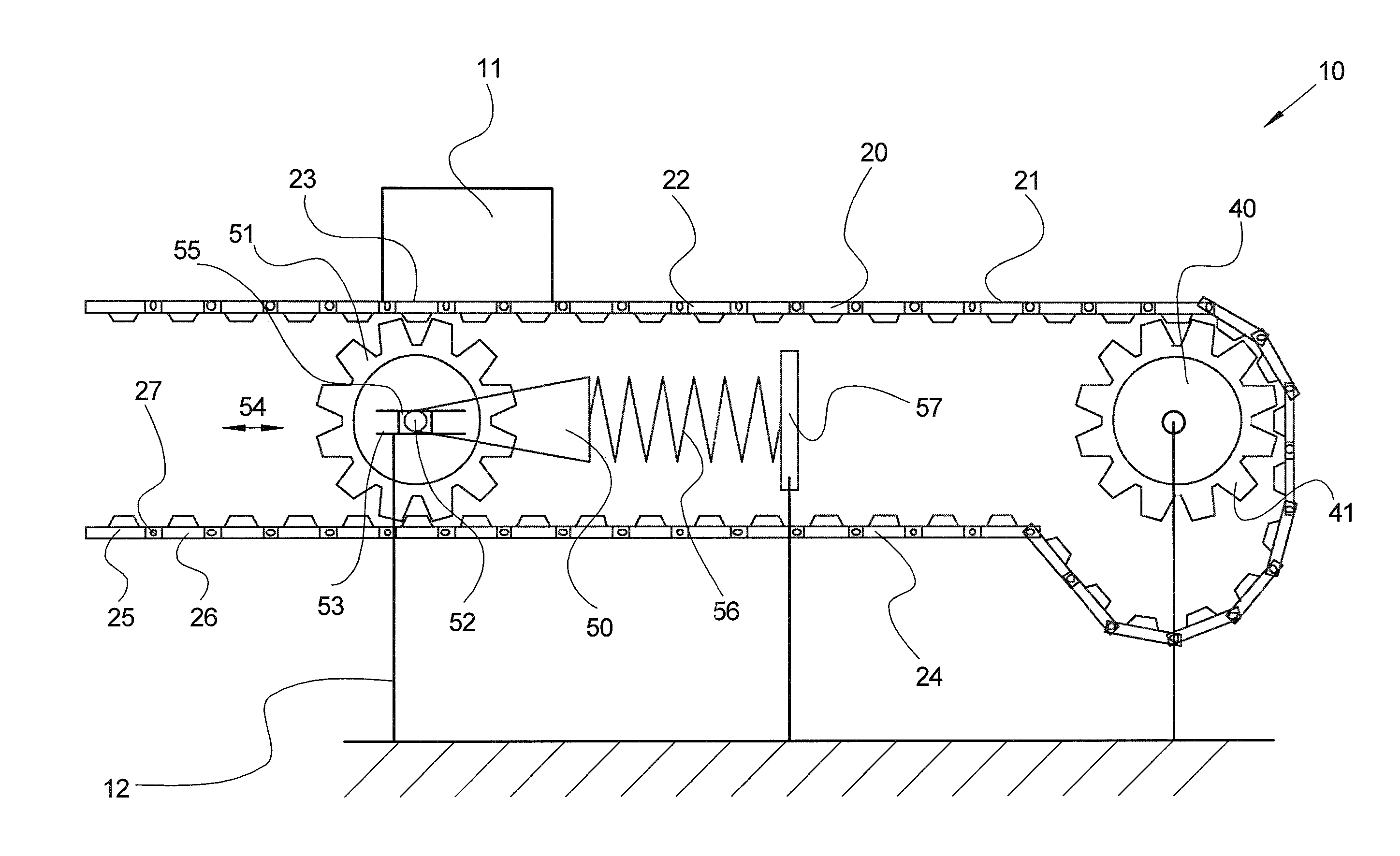
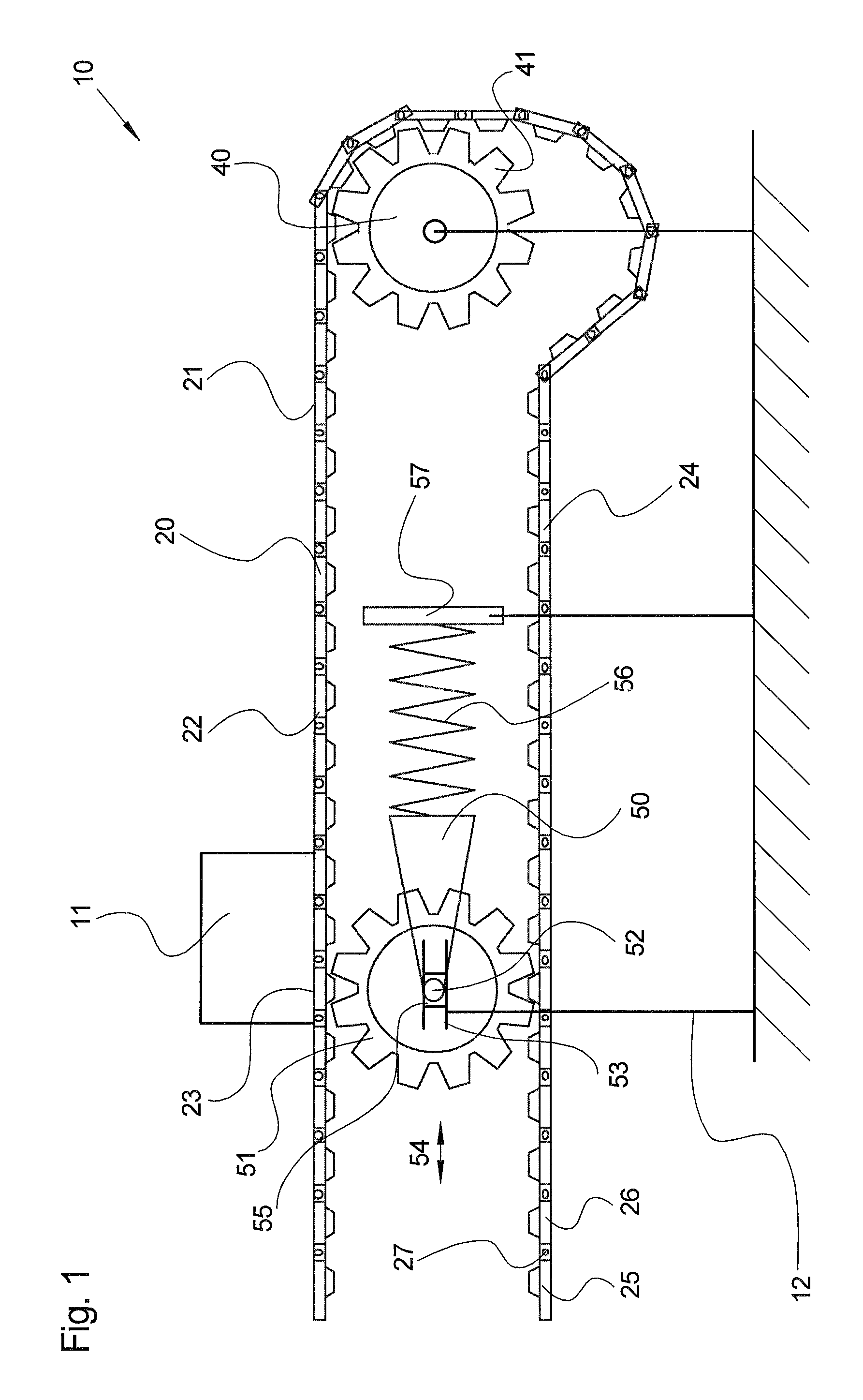
[0019]FIG. 1 shows a conveyor 10 according to the present invention. Conveyor 10 includes an endless conveying means 20, only a subsection of which is shown, however. Endless conveying means 20 is designed as described in U.S. Pat. No. 6,779,652 B2. U.S. Pat. No. 6,779,652 B2 is therefore referenced here and its entire contents are incorporated in the contents of the present application. Accordingly, endless conveyor 20 is a chain conveyor having chain links 25 that are injection-molded of plastic. Each chain link 25 includes a substantially flat transport plate 26, wherein transport plates 26 in totality define a conveying surface 21. It should be noted that, instead of flat transport plate 26, a large number of other transport plates are also known, the shape of which is adapted in a particular manner to goods 11 to be conveyed.

[0020]Every two adjacent chain links 25 are interconnected by a flexible coupling 27 that has two rotational degrees of freedom, thereby enabling conveying...


PUM


Abstract

A conveyor (10) includes at least one endless conveying device (20) having a conveying section (22) having a conveying surface (21), on which conveyed goods (11) can be conveyed. The conveying device (20) are held on a frame (12) using at least two deflection rollers (40), thereby enabling it to circulate endlessly. A driving wheel (51) with a rotary axle (52) is coupled to the conveying device (20) such that the former can be set into a rotational motion by the latter. The rotary axle (52) of the driving wheel (51) is coupled to the damping device (50) such that vibrations in the rotation of the conveying device (20) can be damped. The rotary axle (52) of the driving wheel (51) is supported on the frame (12) such that it can move with translatory motion. The damping device (50) can dampen a translatory motion of the rotary axle (52).

Description

CROSS REFERENCE[0001]The invention described and claimed hereinbelow is also described in de 102009050488.5, filed Oct. 23, 2009. This German Patent Application, whose subject matter is incorporated here by reference, provides the basis for a claim of priority of invention under 35 U.S.C. 119 (a)-(d).BACKGROUND OF THE INVENTION[0002]The present invention relates generally to a conveyor.[0003]A conveyor is known from SU 1 488 216 A1. According to FIG. 1 of SU 1 488 216 A1, the conveyor includes a plurality of endless conveying means in the form of leaf chains. The conveying means have a conveying section with a conveying surface on which conveyed goods 7, 8 can be transported. The conveyed goods are carried along by the conveying means with frictional engagement. The endless conveying means is held on a frame 1 using a plurality of rotatable deflection rollers 3, 4, 5, thereby enabling it to rotate endlessly. According to FIG. 2 in SU 1 488 216 A1, a driving wheel 12 having a rotary ...

Claims


Application Information

Patent Timeline
Patent Type & Authority Patents(United States)
IPC IPC(8): B65G23/04
CPCB65G23/10B65G23/44B65G43/02
Inventor LENORD, OLIVERCHEN, YONGBO
Owner ROBERT BOSCH GMBH
Why Eureka
Try Eureka