Methods and apparatus for improved drilling and milling tools for resection

a drilling and milling tool technology, applied in the field of bone resection, can solve the problems of inability or high resistance of the disclosed tool embodiment, and achieve the effect of facilitating intraoperative and postoperative efficacy and ease of use, and minimizing the tendency of the pilot drill bi

Active Publication Date: 2012-02-14
BIOMET MFG CORP
View PDF471 Cites 14 Cited by
  • Summary
  • Abstract
  • Description
  • Claims
  • Application Information

AI Technical Summary

Benefits of technology

[0011]The present invention provides for embodiments of milling and drilling tools and soft tissue management techniques for arthroplasty facilitating intraoperative and postoperative efficacy and ease of use. In one embodiment, resiliently biased soft tissue protective sleeves surround the side cutting tool and are interposed along the longitudinal axis of the side cutting tool adjacent each side of the bone. The soft tissue protective sleeves are biased to track along the contour of the side of the bone and prevent the side cutting tool from being exposed to soft tissue during the resection. In another embodiment, a pilot drill is initially utilized to create an initial bore in the bone to be resected. The pilot drill preferably has an end cutting arrangement and a non-cutting removal channel that minimizes the tendency of the pilot drill bit to drift off-axis as the initial bore in the bone is created. Once the initial bore is created, the pilot drill bit is withdrawn and a second side cutting tool, such as a milling bit, is then inserted into the bore to perform the desired surface resection.
[0012]The present invention utilizes a number of embodiments of cutting tools to remove boney material to create cut surfaces for prosthetic implant attachment and fixation. The overriding objects of the embodiments are to provide the ability to perform resection in very small incisions, the creation of precise and accurate cut(s), and to provide for soft tissue protection characteristics and features preventing the tool from accidentally harming soft tissue. Specifically, many of the cutting tool embodiments disclosed are either incapable or highly resistant to damaging soft tissue, or are by means disclosed prevented from coming into contact with soft tissue in the first place.
[0013]The present invention utilizes a number of embodiments of cutting guide technologies loosely or directly based on Profile Based Resection (PBR). The overriding objects of PBR technologies are to provide for significantly improved reproducibility of implant fit and alignment in a manner largely independent of the individual surgeon's manual skills, while providing for outstanding ease of use, economic, safety, and work flow performance.
[0014]The present invention utilizes a number of embodiments of alignment or drill guides to precisely and accurately determine the desired cutting guide location / orientation, thus cut surface location(s) / orientation(s), thus prosthetic implant location and orientation. The overriding objects of the embodiments are to precisely and accurately dictate the aforementioned locations and orientations while optionally enabling ease of use in conjunction with manually or Computer Assisted techniques, and while optionally enabling ease of use in minimally invasive procedures where surgical exposure and trauma are minimized.
[0015]The present invention utilizes a number of methods and apparatus embodiments of soft tissue management techniques and the devices supporting said techniques. The overriding object of these embodiments is to take advantage of the anatomy, physiology, and kinematics of the human body in facilitating clinical efficacy of orthopedic procedures.
[0016]It is an often repeated rule of thumb for orthopedic surgeons that a “Well placed, but poorly designed implant will perform well clinically, while a poorly placed, well designed implant will perform poorly clinically.” The present invention provides a method and apparatus for reducing implant placement errors in order to create more reproducible, consistently excellent clinical results in a manner that decreases risk to soft tissue, incision or exposure size requirements, manual skill requirements, and / or visualization of cutting action.

Problems solved by technology

Specifically, many of the cutting tool embodiments disclosed are either incapable or highly resistant to damaging soft tissue, or are by means disclosed prevented from coming into contact with soft tissue in the first place.

Method used


Image

  • Methods and apparatus for improved drilling and milling tools for resection
  • Methods and apparatus for improved drilling and milling tools for resection
  • Methods and apparatus for improved drilling and milling tools for resection

Examples


embodiment 200

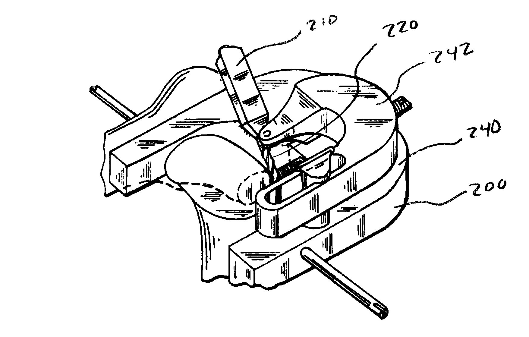
[0039]FIGS. 16 through 21 describe another embodiment 200 of the present invention. As shown in FIG. 16, this embodiment includes a Base 240 and a Rotational / Translational Pivot Arm 242 coacting to allow for infinite manipulation of the bushing 210 pivot pin 214 location within a desired plane during the process of removing material from the proximal tibia or other bone. Movement of the Rotational / Translational Pivot Arm 242 in both rotational and translational degrees of freedom within a desired plane allows for any combination of rotational and translational movement of the axis of the bushing pivot pin 214 within its desired plane. In other words, this embodiment of the present invention allows for infinite and continuous adjustability of cutting tool 220 location and orientation with respect to the bone or bones being cut while providing for accurate and precise cut surface creation.

[0040]FIGS. 22 through 28 represent another embodiment 200 of the present invention whose princip...

embodiment 300

[0041]FIGS. 29 and 30 show an embodiment 300 of the present invention directed toward endplate preparation in spinal reconstruction where the endplates are prepared to receive a prosthetic implant. Guide 300 includes a milling handle 302 to which the cutting tool 310 attaches. It is interesting to note that the profile of the cutting path 312 of the guide 300 represented in FIG. 30, in this embodiment, is geometrically identical to the cutting path of the resected surface created by the passage of the cutting tool 310 shown. This could be very helpful in clinical application where such a device where inserted into a wound such that, while the surgeon could not visually observe the cutting tool 310 while it removes boney material, he could, by way of the guide geometry, observe where the cutting is with respect to the bone being cut by looking at the position (represented by “POS 1” and “POS 2”) of ‘Pivot 2’, represented in FIG. 30, with respect to its location in contact with the gu...

embodiment 400

[0048]FIGS. 35-40 shows an embodiment 400 of the present invention wherein the guide plates 402 and guide surfaces 404 are located entirely outside the wound, but the side cutting drill 420 and handle 422 construct are not passed through mediolateral soft tissue portals described hereinabove. The side cutting drill controlling portion 424 of the handle is essentially ‘snaked’ into the less invasive wound / exposure / approach / incision and the guide engagement features 426 are engaged to the cutting guide at a location entirely outside the wound. As long as the axis of the engagement feature 426 is maintained as coaxial with the side cutting drill 420, the desired cut geometries will be attained despite manipulation of the handle 422 with respect to the guide 402. This method can be utilized to complete some or all of the desired cuts. Also, this embodiment of the current invention can be used to perform the posterior cut, posterior chamfer cut, and distal cut optionally using kinematic ...


PUM


Abstract

Milling and drilling tools and soft tissue management techniques are provided for arthroplasty that facilitate intraoperative and postoperative efficacy and ease of use. In one embodiment, resiliently biased soft tissue protective sleeves surround a side cutting tool and are interposed along the longitudinal axis of the cutting tool, preferably adjacent each side of the bone. The soft tissue protective sleeves are biased to track along the contour of the side of the bone and prevent the cutting tool from being exposed to soft tissue during the resection. In another embodiment, a pilot drill is initially utilized to create an initial bore in the bone to be resected. The pilot drill preferably has an end cutting arrangement and a non-cutting removal channel that minimizes the tendency of the pilot drill bit to drift off-axis as the initial bore in the bone is created. Once the initial bore is created, the pilot drill bit is withdrawn and a second side cutting tool, such as a milling bit, is then inserted into the bore to perform the desired surface resection.

Description

CLAIM TO PRIORITY[0001]The present invention claims priority to U.S. Provisional Application No. 60 / 551,262, filed Mar. 8, 2004, entitled, “METHODS AND APPARATUS FOR IMPROVED DRILLING AND MILLING TOOLS FOR RESECTION,” and claims priority to U.S. Provisional Application No. 60 / 551,080, filed Mar. 8, 2004, entitled, “METHODS AND APPARATUS FOR PIVOTABLE GUIDE SURFACES FOR ARTHROPLASTY,” and claims priority to U.S. Provisional Application No. 60 / 551,078, filed Mar. 8, 2004, entitled, “METHODS AND APPARATUS FOR MINIMALLY INVASIVE RESECTION,” and claims priority to U.S. Provisional Application No. 60 / 551,096, filed Mar. 8, 2004, entitled, “METHODS AND APPARATUS FOR ENHANCED RETENTION OF PROSTHETIC IMPLANTS,” and claims priority to U.S. Provisional Application No. 60 / 551,631, filed Mar. 8, 2004, entitled, “METHODS AND APPARATUS FOR CONFORMABLE PROSTHETIC IMPLANTS,” and claims priority to U.S. Provisional Application No. 60 / 551,307, filed Mar. 8, 2004, entitled, “METHODS AND APPARATUS FOR I...

Claims


Application Information

Patent Timeline
Patent Type & Authority Patents(United States)
IPC IPC(8): A61B17/00
CPCA61B17/15A61B17/1757A61B17/1764A61F2/38A61F2/3859A61B17/155A61B17/157A61B17/1671A61B17/1675A61B2017/1602A61F2002/3895A61F2310/00011
Inventor HAINES, TIMOTHY G.
Owner BIOMET MFG CORP
Why Eureka
Try Eureka