
System, method, and program product for synthesizing non-thermodynamically constrained heat exchanger networks

a heat exchanger network and non-thermodynamically constrained technology, applied in the field of energy recovery systems, to achieve the effect of facilitating easy-to-implement future retrofit, substantial capital cost reduction, and improving capability

Active Publication Date: 2012-02-14
SAUDI ARABIAN OIL CO
View PDF26 Cites 15 Cited by
  • Summary
  • Abstract
  • Description
  • Claims
  • Application Information

AI Technical Summary

Benefits of technology

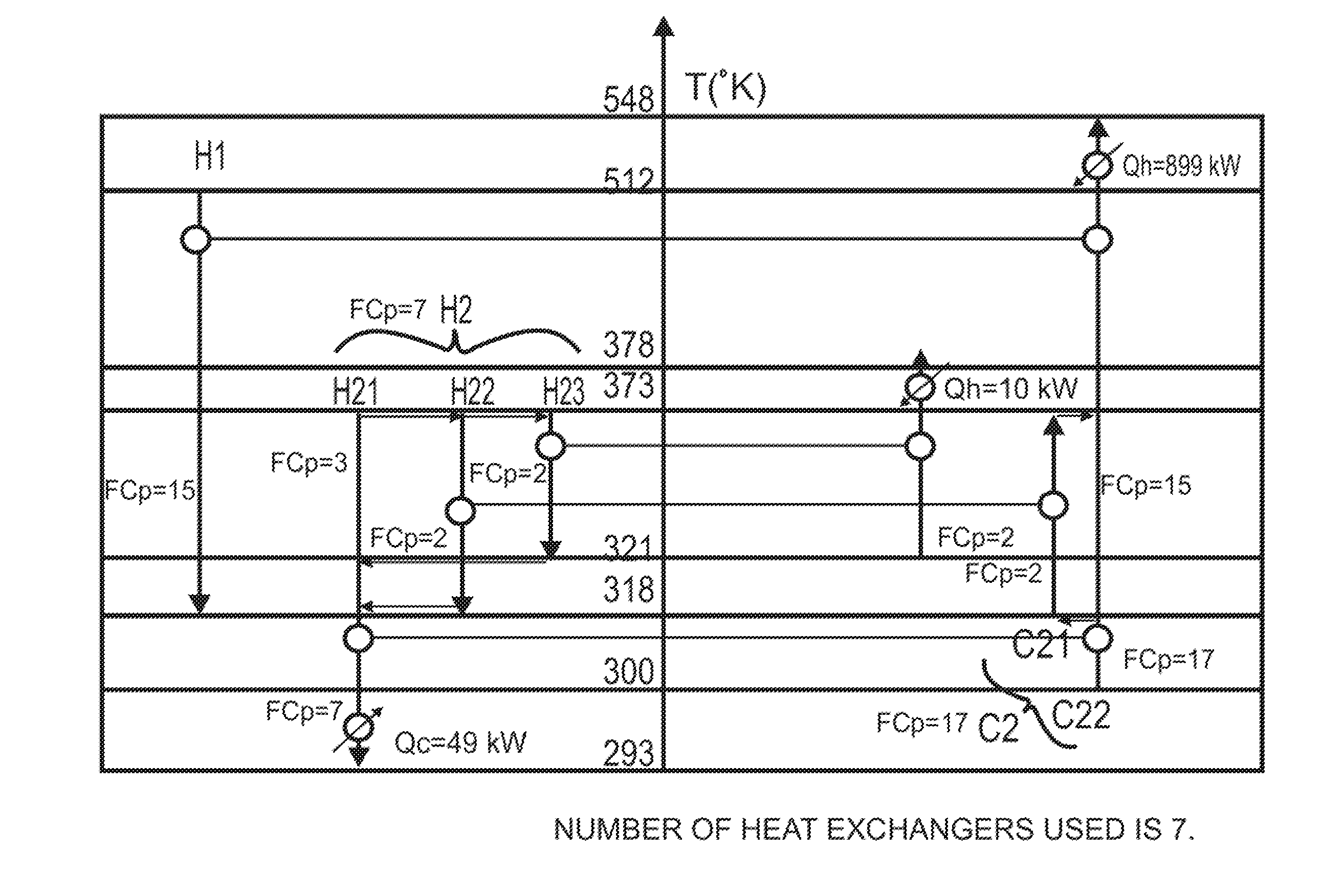
[0017]Various embodiments of the present invention also advantageously provide improved methods, systems, and program product that can process / employ certain situations / constraints / opportunities that can render better economics from an energy point of view, capital point of view, or both energy and capital points of view, such as, for example: stream-specific minimum temperature approaches (values) ΔTmini, e.g., considered as optimization parameters (where the superscript “i” represents the specific hot stream); situations in which a hot stream is matched with one or more hot streams and / or a cold stream is matched with one or more cold streams; or situations in which a hot stream is partially converted to a cold stream and / or a cold stream is partially converted to hot stream, to thereby render a heat exchanger network having an optimal number of the exchangers. Various embodiments of the present invention beneficially also provide an improved method, system and program product to synthesize a heat exchanger network, which can employ streams splitting to reduce energy quality degradation caused by matching a hot stream at a certain temperature interval at the process sink region with one or more cold streams at lower temperature intervals.
[0046]Advantageously, various embodiments of the present invention exhibit substantial improvements in capability over that of the pinch design method, while still keeping the process engineer in the loop of designing his / her heat exchanger network. Various embodiments of the present invention also render on the conceptual level, several improvements over the pinch design method. For example, while the pinch design method cannot account for or employ (1) stream-specific minimum approach temperatures, (2) situations in which a hot stream is matched with another hot stream and / or a cold stream is matched with another cold stream, and (3) situations in which a hot stream is partially converted to a cold stream and / or a cold stream is partially converted to a hot stream, various embodiments of the present invention can indeed manage such constraints / configuration profiles, systematically, to synthesize an improved heat exchanger network design over that possible using prior methodologies. Further, by solving the problem as a single problem, rather than decomposing the problem into an above-the-pinch problem, a below-the-pinch problem, and an at or near the pinch problem, as is done in the various pinch design methods, various embodiments of the present invention can render at least a lesser number of heat exchange units for the same energy targets compared with networks synthesized using the pinch design method, as well as render network configurations that facilitate easy-to-implement future retrofit. This is particularly the case for the problems that exhibit multiple pinches, for pinch problems with near pinch applications, and for threshold problems. Still further, such advanced systematic methods / techniques can advantageously benefit the heat exchangers network synthesis and waste heat recovery applications of non-constrained, thermodynamically constrained, and non-thermodynamically constrained new plant designs and its future retrofit in a dynamic world of significant changes in energy availability and prices.

Problems solved by technology

As such, the heat exchanger network synthesis problem has arguably been one of the most studied problems in the field of process synthesis in the last four decades.
The systematic synthesis of heat exchangers network, however, has proven to be a challenging task.
Although such methods have been in academia since the late eighties, they are still not widely used on a large scale in industrial applications for several reasons.
The academics claim that the reasons behind this are: (1) that the computational requirements of such methods are substantial, especially for large problems; and (2) that the resultant solution, in general, can not guarantee globality.
Other significant obstacles include the black box nature of the methods, the assumptions regarding problem economics, the types of heat exchangers used in the network (shell & tube, twisted tube, plate and frame types, etc.), the need to know the several utilities types and temperatures beforehand, and the non-inclusive nature of the “transshipment model” used for streams matching and superstructure application.
In superstructure construction where it is required for the designer to know ahead of time just how many times a stream or one of its branches are going to meet another stream, however, the transshipment model is inadequate as it does not include or account for various situations, such as, for example: those in which it would be beneficial to allow the optimization process to select the utility types and supply temperatures to be used; those in which it would be beneficial for one or more streams to change their identities; and those in which it would be beneficial for one or more utilities streams to effectively become process streams, and so on, or consider the effect of including such possibilities on such streams superstructures.
Also recognized is that, in addition, software applications that use the pinch design method or that use the pinch design method as a basis for its initial design followed by the optimization option for branches and duties can not handle certain situations / constraints / opportunities that can render better economics, for example, from energy, capital, or both points of view, which means that some superior network designs will never be synthesized using such applications.
For example, such software applications do not systematically handle or allow for: stream-specific minimum approach temperatures; situations in which a hot stream is matched with a hot stream and / or a cold stream is matched with one or more cold streams; or situations in which a hot stream is partially converted to a cold stream and / or a cold stream is partially converted to hot stream.
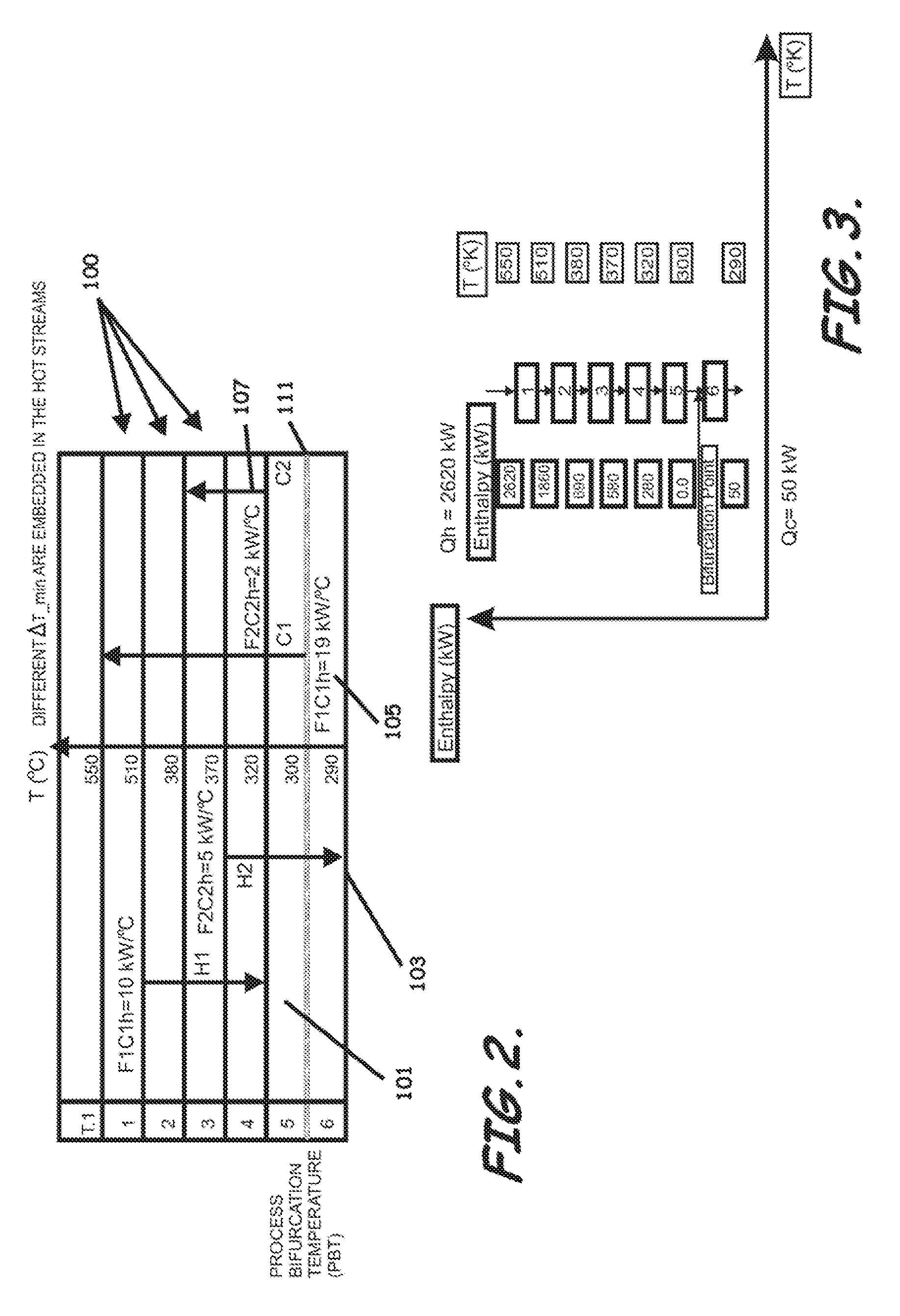
Where the pinch design method performs matching at the pinch point, e.g., at a medial point along the temperature scale extending between maximum and minimum target and supply temperatures, and moves up on the temperature scale to complete the sub-problem above the pinch point, and then starts again at the pinch point and moves down at the temperature scale to complete the sub-problem below the pinch point, which can result in unnecessary constraints solved by splitting of streams and which can correspondingly result in a network with an excessive number of units, the inventor has recognized that by performing matching between the hot streams and utilities with the cold streams beginning, for example, at the highest temperature or temperature interval on the temperature scale and then proceeding from that point, top to bottom, the streams can be matched at the same temperature interval (where the temperature approach between the hot and cold streams are minimum), which can allow the balance / difference between the supply of the heat and the demand of the cold to be compensated for by a utility or utilities with the lowest possible supply temperature.
Further, recognized by the inventor is that it is not only unnecessarily, but imprudent, to treat threshold problems that do not have pinch constraints as a pinch problem merely to generalize the pinch design method for handling all types of problems, as is the case in the pinch design method, because doing so creates a constrained situation in a problem that does not have such constraints.
Such unnecessary addition of constraints resultingly necessitates splitting of streams at the factious pinch point again to satisfy the matching criteria at the pinch according to the pinch design method rules, which correspondingly results in a network with an excessive number of heat exchanger units.
Notably, it is not believed that the pinch design method could adopt retrofitability during the design stage as it does not have a systematic method to select an optimal set of stream specific minimum temperature, either in general, or based upon a trade-off between capital and energy costs, in particular, and because its pinch design philosophy starts the design of the network only after selecting an optimal network global minimum approach temperature using, for example, the “SUPERTARGET” method which targets for both energy consumption and the heat exchanger network area at the same time.
Even by repeating such sequential philosophy using the global minimum temperature approach, the resulting new network structure would not be expected to consistently resemble the previous network structure, in class, and thus, would result in a requirement for an undue expenditure in network reconciliation efforts, to try to form a continuum of common-structure heat exchanger network designs which can be used to facilitate user selection of a physical heat exchanger network structure satisfying both current user-selected economic criteria and anticipated potential future retrofit requirements and corresponding physical heat exchanger network development and facility surface area of allotment based upon such selected design.

Method used


Image

  • System, method, and program product for synthesizing non-thermodynamically constrained heat exchanger networks
  • System, method, and program product for synthesizing non-thermodynamically constrained heat exchanger networks
  • System, method, and program product for synthesizing non-thermodynamically constrained heat exchanger networks

Examples


Embodiment Construction

[0084]The present invention will now be described more fully hereinafter with reference to the accompanying drawings, which illustrate embodiments of the invention. This invention may, however, be embodied in many different forms and should not be construed as limited to the illustrated embodiments set forth herein. Rather, these embodiments are provided so that this disclosure will be thorough and complete, and will fully convey the scope of the invention to those skilled in the art. Like numbers refer to like elements throughout Prime notation, if used, indicates similar elements in alternative embodiments.

[0085]As noted previously, the total energy employed or consumed by the processes of a superstructure can be optimized to a global minimal level, for example, through careful placement and configuration of specific material streams with respect to one another and through application of a heat exchangers network (HEN) to allow waste heat recovery. In grassroots plants design and ...


PUM


Abstract

Systems, methods, and program product to synthesize a grass-roots heat exchanger network for non-thermodynamically constrained problems for a plurality of hot process streams to be cooled and a plurality of cold process streams to be heated according to a plurality of utilities targets, are provided. An exemplary system includes a heat exchange network synthesizing computer and heat exchange network synthesizing program product configured to analyze the waste heat recovery problem without decomposition to produce a result having an optimal number of network heat exchanger units through application of advanced process-to-process matching schemes for non-thermodynamically constrained problems.

Description

BACKGROUND OF THE INVENTION[0001]1. Related Applications[0002]This application is a non-provisional of and claims priority to U.S. Provisional Patent Application No. 61 / 256,754, filed Oct. 30, 2009, titled “System, Method, and Program Product for Synthesizing Non-Constrained and Constrained Heat Exchanger Networks and Identifying Optimal Topology for Future Retrofit”; is a continuation-in-part of and claims priority to and the benefit of U.S. patent application Ser. No. 12 / 575,743, filed Oct. 8, 2009, titled “System, Method, and Program Product for Targeting and Identification of Optimal Process Variables in Constrained Energy Recovery Systems”; and is related to U.S. patent application Ser. No. 12 / 767,217, filed Apr. 26, 2010, titled “System, Method, and Program Product for Synthesizing Non-Constrained and Constrained Heat Exchanger Networks,” U.S. patent application Ser. No. 12 / 767,315, filed Apr. 20, 2010, titled “System, Method, and Program Product for Synthesizing Heat Exchange...

Claims


Application Information

Patent Timeline
Patent Type & Authority Patents(United States)
IPC IPC(8): G06F19/00
CPCF01K13/02
Inventor NOURELDIN, MAHMOUD BAHY
Owner SAUDI ARABIAN OIL CO
Learn More