Method of controlling brake power for a vehicle with an electrically variable transmission

a technology of electrically variable transmission and transmission, which is applied in the direction of process and machine control, battery/fuel cell control arrangement, instruments, etc., can solve the problems of engine fan causing significant parasitic load and excessive energy from vehicle braking

Inactive Publication Date: 2012-02-14
GM GLOBAL TECH OPERATIONS LLC
View PDF8 Cites 13 Cited by
  • Summary
  • Abstract
  • Description
  • Claims
  • Application Information

AI Technical Summary

Problems solved by technology

However, if the battery has a sufficient state of charge then the excess energy from vehicle braking must be dissipated.
For heavy duty vehicles in particular the engine fan represents a significant parasitic load on the power train which is most cases is provided directly from fuel supplied to the engine.

Method used


Image

  • Method of controlling brake power for a vehicle with an electrically variable transmission
  • Method of controlling brake power for a vehicle with an electrically variable transmission
  • Method of controlling brake power for a vehicle with an electrically variable transmission

Examples


Embodiment Construction

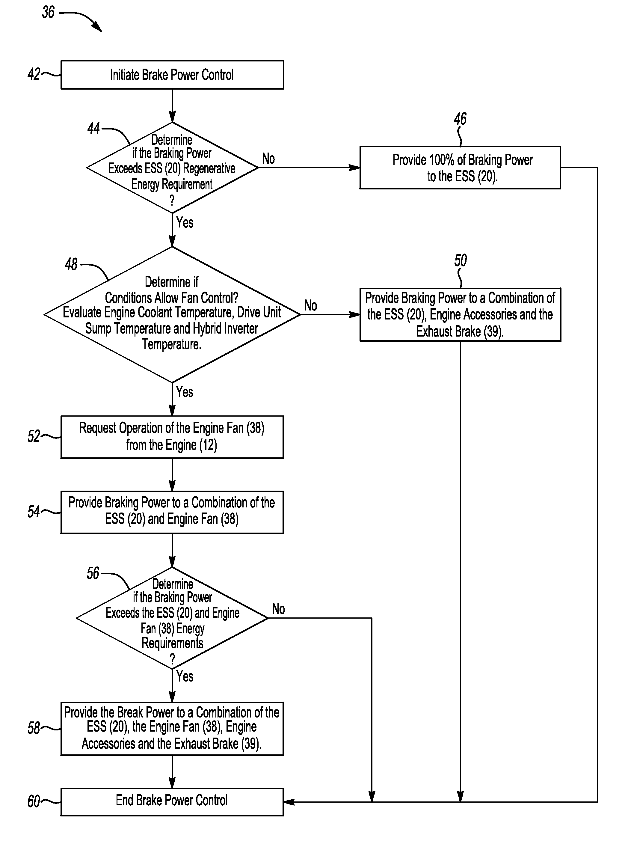
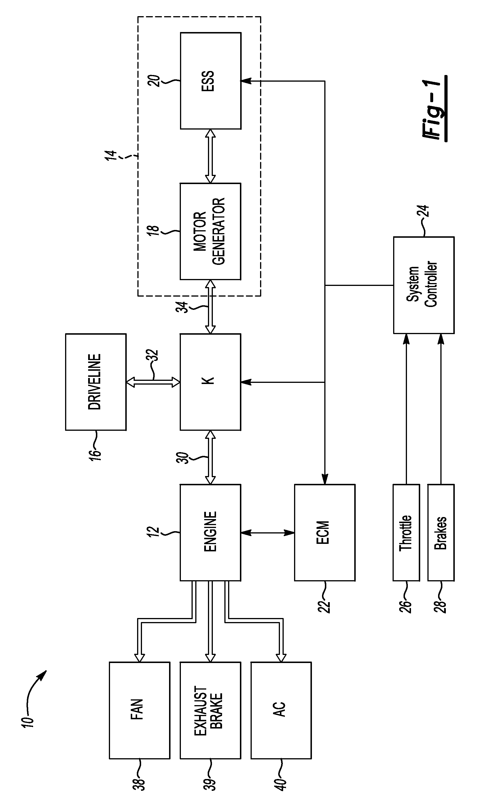
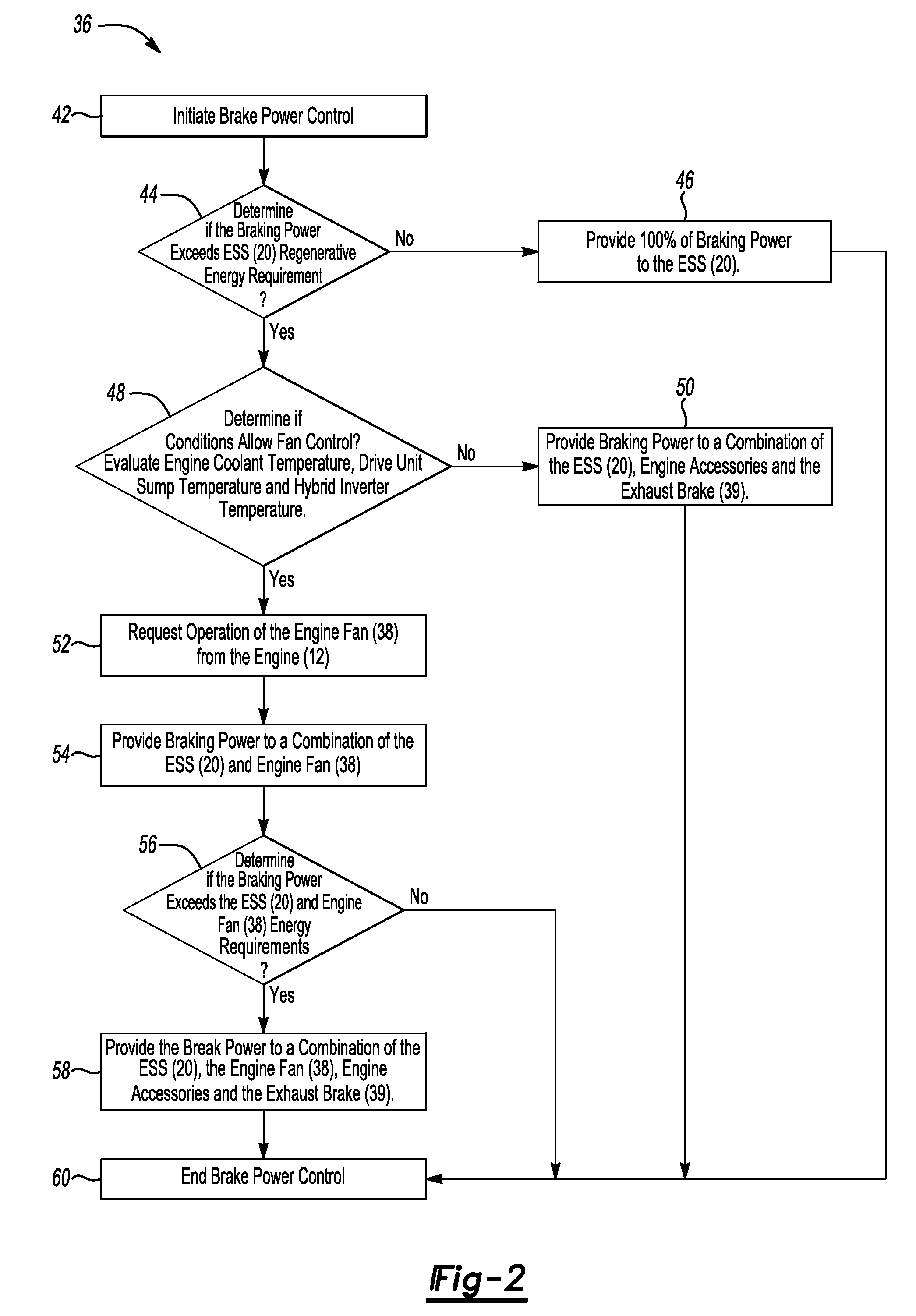
[0007]Referring to the Figures, wherein like reference numbers refer to the same or similar components throughout the several views, FIG. 1 schematically illustrates a heavy duty hybrid vehicle 10 including an engine 12, an electrically variable transmission 14, and a vehicle driveline 16. The transmission 14 includes at least one motor / generator 18 and an energy storage system (ESS) 20. The at least one motor / generator 18 may be two motor / generators 18 often referred to as motors A and B. Typically, the ESS 20 is one or more batteries in a battery pack module. Any appropriate energy storage means capable of bidirectional electrical energy flow may be used. The ESS 20 also includes various controllers, sensors, and a microprocessor for diagnosis and control of the battery pack.

[0008]An engine control module (ECM) 22 is connected to the engine 12 and includes a microprocessor (not shown) for controlling the engine 12. The ECM 22 communicates with a system controller 24. The system co...


PUM


Abstract

A method of controlling brake power flow for a vehicle with an electrically variable transmission is provided. When the brake power exceeds a power absorption capability of the energy storage system, then vehicle conditions are evaluated to determine if control of an engine fan is allowable. When conditions allow for fan control then the remaining brake power is provided for operation of the engine fan. Any excess brake power is dissipated through the exhaust brake or used by other vehicle accessories.

Description

TECHNICAL FIELD[0001]The present invention relates, generally, to a vehicle having an electrically variable transmission, and more specifically, to a system for managing regenerative braking power for the electrically variable transmission.BACKGROUND OF THE INVENTION[0002]Vehicles with electrically variable transmissions are commonly driven in part by the transmission including the associated battery and motor / generators. Excess energy from vehicle operation is stored in the battery. The large amounts of kinetic energy from braking are converted to electrical energy and may be used to regenerate the battery charge. However, if the battery has a sufficient state of charge then the excess energy from vehicle braking must be dissipated. Typically, for large vehicles this energy is dissipated through engine / driveline retarder braking and the vehicle service brakes, also known as exhaust braking. The engine retard braking may be coordinated by the vehicle and is not necessarily operator ...

Claims


Application Information

Patent Timeline
Patent Type & Authority Patents(United States)
IPC IPC(8): H02P3/04B60K6/00G06F19/00B60W30/18
CPCB60L7/18B60L11/1861B60W10/06B60W10/08B60W10/184B60W10/198B60W30/18127B60W30/18136B60L2240/525B60W20/00B60W2510/244Y02T10/6286Y02T10/7005Y02T10/7044Y02T10/705B60L58/15Y02T10/62Y02T10/70B60W20/13B60W10/26
Inventor HUSEMAN, STEVEN C.
Owner GM GLOBAL TECH OPERATIONS LLC
Why Eureka
Try Eureka