Measuring quantum states of superconducting resonators

a superconducting resonator and quantum state technology, applied in the field of quantum computing, can solve the problems of cumbersome and relatively time-consuming process of resonator state to the qubit and the dc squid

Active Publication Date: 2012-02-14
IBM CORP
View PDF8 Cites 9 Cited by
  • Summary
  • Abstract
  • Description
  • Claims
  • Application Information

AI Technical Summary

Problems solved by technology

Previous methods of measuring the quantum state of a resonator may undesirably change the quantum state; and transferring the resonator state to the qubit and the DC SQUID is a cumbersome and relatively time consuming process.

Method used


Image

  • Measuring quantum states of superconducting resonators
  • Measuring quantum states of superconducting resonators
  • Measuring quantum states of superconducting resonators

Examples


Embodiment Construction

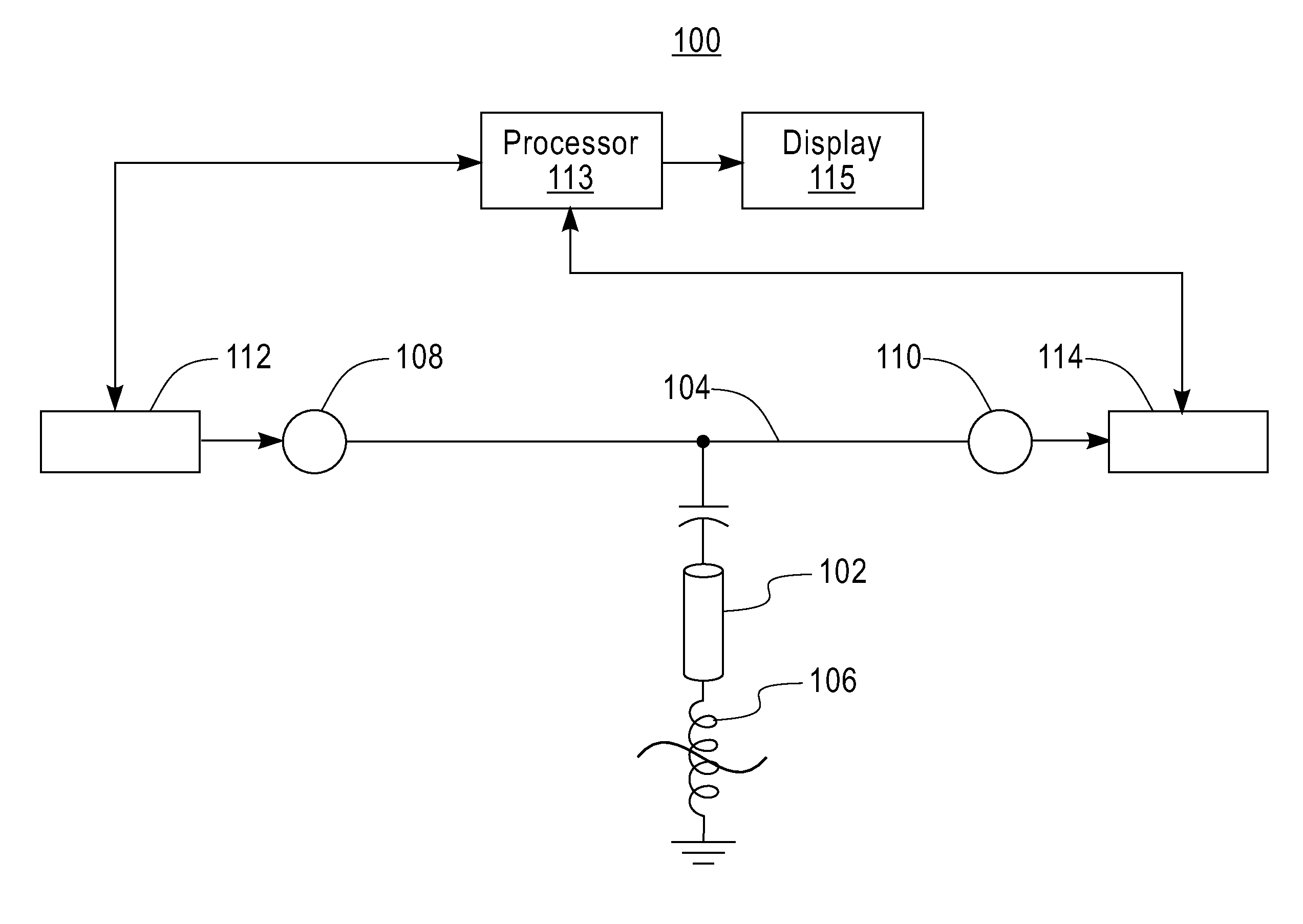
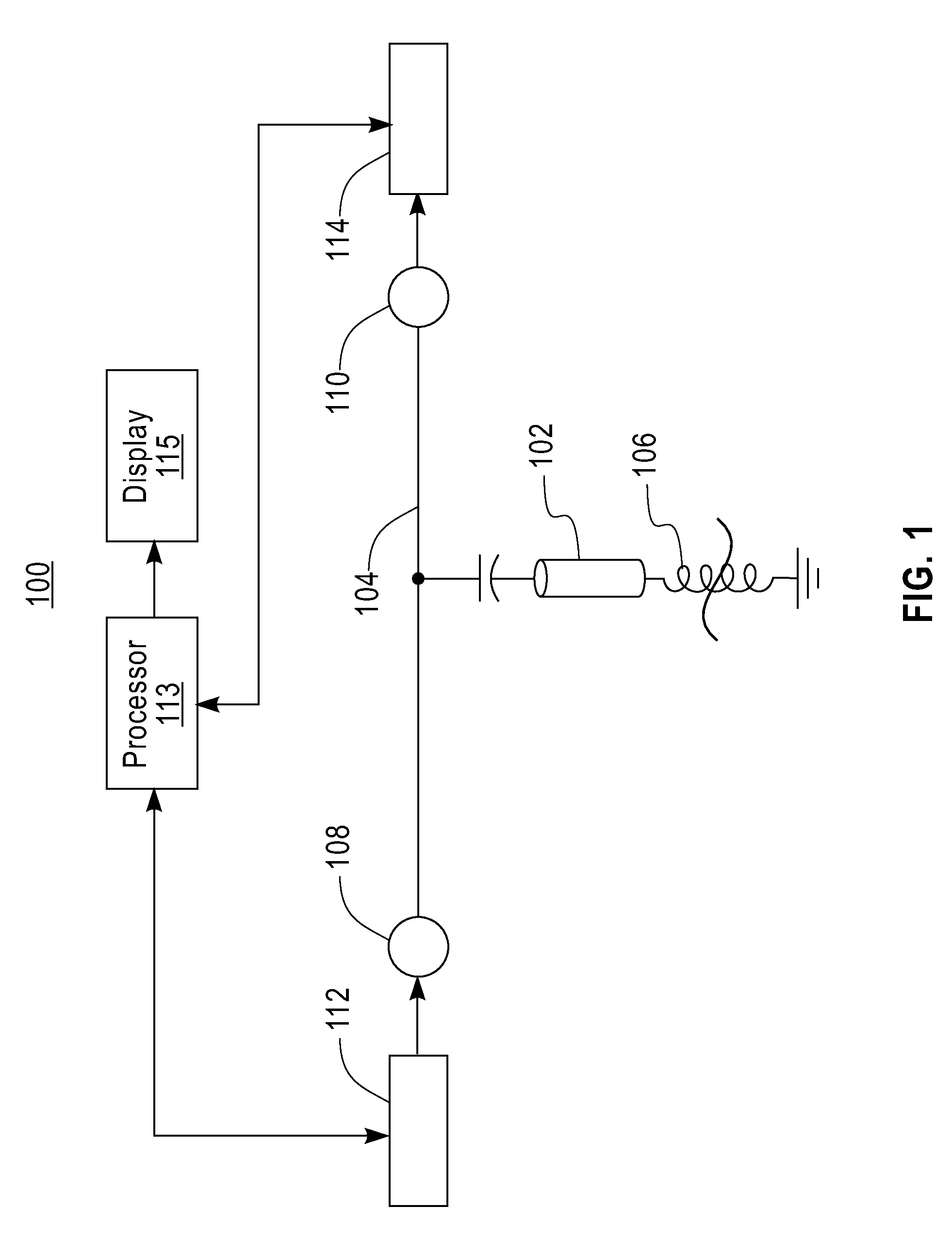
[0011]A method and system for measuring the quantum state of a superconducting resonator by performing microwave readout is described below. FIG. 1 illustrates an exemplary embodiment of a circuit having a quantum state that may be read using the methods described below. The method described allows the determination of the quantum state of the first mode of the resonator by measuring the shift in frequency response of the resonator at a second mode. The method allows the quantum state of a resonator to be determined without undesirably changing the quantum state of the resonator.

[0012]In this regard, FIG. 1 includes a system 100 having a resonator 102 that may include, for example, a transmission line resonator, a distributed half-wave resonator, lumped element resonator coupled to a feed line 104, and terminated to ground through a nonlinear element 106. The nonlinear element is a reactive element having capacitive or inductive properties. Examples of a nonlinear element include a ...


PUM


Abstract

A method for measuring the quantum state of a resonator includes, exciting an input port of a circuit with signal, measuring a phase shift of the signal at an output port of the circuit, wherein the resonator is coupled to the input and the output ports, and calculating a quantum state of the resonator as a function of the measured phase shift of the signal.

Description

FIELD OF INVENTION[0001]The present invention relates to quantum computing, and more specifically, to a system and method for measuring the quantum state of superconducting resonators.DESCRIPTION OF RELATED ART[0002]Superconducting resonators are often used in circuits for quantum computers. Methods for measuring the state of a superconducting resonator include coupling the resonator to a qubit and implementing a dispersive readout, and transferring the resonator state to the qubit and reading the state with a DC Superconducting Quantum Interference Device (SQUID). Previous methods of measuring the quantum state of a resonator may undesirably change the quantum state; and transferring the resonator state to the qubit and the DC SQUID is a cumbersome and relatively time consuming process.BRIEF SUMMARY[0003]According to one aspect of the present invention, a method for measuring the quantum state of a resonator includes, exciting an input port of a circuit with signal, measuring a pha...

Claims


Application Information

Patent Timeline
Patent Type & Authority Patents(United States)
IPC IPC(8): G06F15/00
CPCB82Y10/00G06N99/002G06N10/00G06N10/40
Inventor DIVINCENZO, DAVIDKEEFE, GEORGE A.KUMAR, SHWETANKSTEFFEN, MATTHIAS
Owner IBM CORP
Why Eureka
Try Eureka