Energy dissipating assembly for frame walls

Inactive Publication Date: 2012-02-21
MUELLER LEE W +1
View PDF17 Cites 12 Cited by
  • Summary
  • Abstract
  • Description
  • Claims
  • Application Information

AI Technical Summary

Benefits of technology

[0034]In one embodiment, the plurality of deformable members respond to a reversed cyclic shear force at the top portion of the wall by deforming during each displacement of the top portion of the wall relative to the foundation, thereby increasing the energy dissipation of the rev

Problems solved by technology

Lateral loads (for example those induced by earthquakes and hurricane/tornado winds) are unpredictable in both occurrence and magnitude.
As a result, failure of any one of these common elements under one loading condition (say lateral) can compromise the integrity of the entire system under the other condition.
The details of how a shear wall resists lateral load are quite complex.
That is, to develop a certain level of lateral resistance under the design event, these systems must undergo significant inelastic deformation (damage) which in turn results in damage to the contents and other non-structural components of the building.
Furthermore, conventional shear walls and other prefabricated panel systems used in l

Method used


Image

  • Energy dissipating assembly for frame walls
  • Energy dissipating assembly for frame walls
  • Energy dissipating assembly for frame walls

Examples


Embodiment Construction

[0054]This application is a continuation-in-part of U.S. patent application Ser. No. 09 / 932,181, filed on Aug. 17, 2001, entitled “A-FRAME SHEAR ASSEMBLY FOR WALLS,” which is hereby incorporated by reference in its entirety.

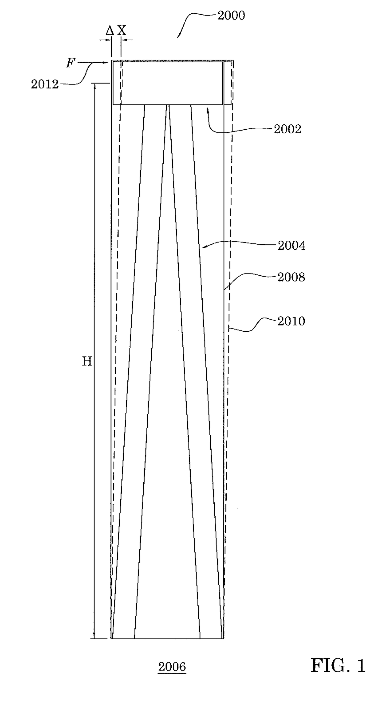
[0055]The present teachings relate to a deformable energy dissipating assembly that couples the top portion of a wall frame to the foundation. FIG. 1 shows a block diagram of one embodiment of a shear assembly 2000 having a deformable energy dissipating assembly 2002. As described below, the energy dissipating assembly 2002 can be attached to the top portion of a frame 2008 in different manners. The energy dissipating assembly 2002 can also be attached to an interconnecting assembly 2004 so that the interconnecting assembly 2004 couples the energy dissipating assembly 2002 to a foundation 2006.

[0056]As described below in greater detail, the shear assembly 2000 can be implemented in light metal frame structures as well as wood frame structures. The shear assembly ...


PUM


Abstract

Lateral motion devices are used in conjunction with relatively rigid shear assemblies to further dissipate shear forces on frame construction buildings. In one embodiment, the lateral motion device is interposed between the shear assembly and the upper portion of the wall to permit relative motion therebetween and to absorb and dissipate a portion of the energy associated with shear force through spring-like behavior and deformation. In one embodiment, the energy dissipation is achieved by a plurality of corrugation structures, where the top of the corrugation is attached to the upper portion of the wall and the bottom of the corrugation is attached to an interconnecting assembly that is securely attached to the foundation. Placing the energy dissipating device near the upper portion of the wall mounted on a comparatively rigid frame provides a relatively short moment arm with respect to the lateral forces imposed by the wall on the energy dissipating device to allow better control of the response to the shear force.

Description

RELATED APPLICATIONS[0001]This application is a continuation of U.S. application Ser. No. 10 / 891,421, filed Jul. 13, 2004, now abandoned entitled “ENERGY DISSIPATING ASSEMBLY FOR FRAME WALLS” which is a continuation-in-part of U.S. patent application Ser. No. 09 / 932,181, filed on Aug. 17, 2001, now U.S. Pat. No. 6,761,001 entitled “A-FRAME SHEAR ASSEMBLY FOR WALLS,” which are hereby incorporated by reference in their entirety. This application also claims the benefit of U.S. Provisional Application No. 60 / 226,354, filed on Aug. 18, 2000, entitled “A-FRAME SHEAR ASSEMBLY FOR WALLS.”BACKGROUND[0002]1. Field[0003]The present teachings relates to the construction industry and, in particular, concerns systems and methods for providing improving lateral strengthening and performance of wall structures using a shear assembly with energy-dissipating attachment members.[0004]2. Description of the Related Art[0005]Low-rise, commercial, institutional and residential (single and multi-family) b...

Claims


Application Information

Patent Timeline
IPC IPC(8): E04H9/00E04H9/02E04B1/98E04B1/343
CPCE04H9/02E04H9/028E04H9/0237
Inventor MUELLER, LEE W.SERRETTE, REYNAUD L.
Owner MUELLER LEE W
Why Eureka
Try Eureka