
Hollow speed reducer

a technology of speed reducer and speed reduction plate, which is applied in the direction of gearing, oblique crank gearing, wobble plate gearing, etc., to achieve the effect of facilitating manufacturing, reducing the length in an axial direction of the turning structure, and not significantly changing the structure per s

Active Publication Date: 2012-02-21
NABLESCO CORP
View PDF21 Cites 15 Cited by
  • Summary
  • Abstract
  • Description
  • Claims
  • Application Information

AI Technical Summary

Benefits of technology

The present invention relates to a speed reducer for a robot or other machine that can be used to reduce the speed of a motor or output of a drive motor. The invention provides a hollow speed reducer with a hollow hole at the center, which allows for a smaller size of the turning structure of the machine. The invention also includes a plurality of small-sized motors that can be used to further shorten the length of the turning structure. The speed reducer can be used as it is with only minor modifications, and the invention allows for the continuous operation of the machine even if one of the motors fails. This reduces the time it takes to fix the problem and get the machine back in production.

Problems solved by technology

According to the speed reducer disclosed in Patent Reference 1, there is a problem that the motor is large-sized, and therefore, a turning structure is large-sized, particularly, a length in an axial direction is large.

Method used


Image

  • Hollow speed reducer
  • Hollow speed reducer
  • Hollow speed reducer

Examples


Embodiment Construction

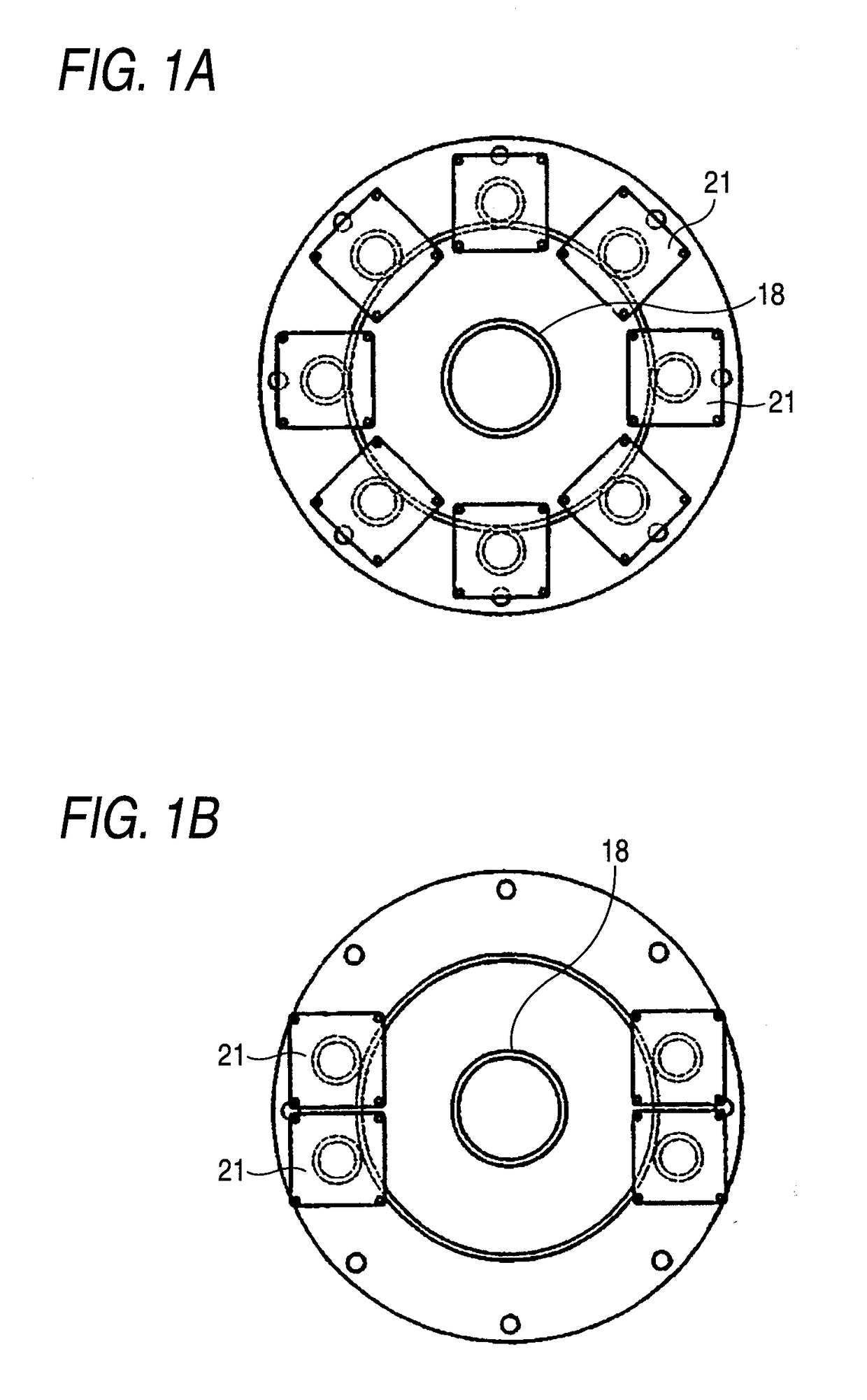
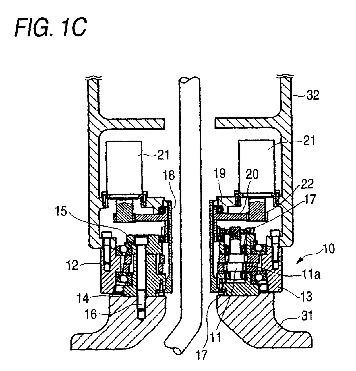
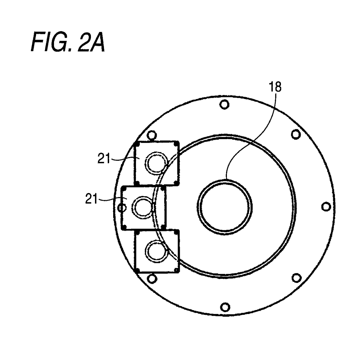
[0030]A number of embodiments of the invention will be explained in reference to the attached drawings as follows. FIGS. 1A through C show an embodiment of constituting a turning mechanism of a robot arm by using a planetary gear apparatus as a hollow speed reducer according to the invention, FIG. 1A is a plan view of a first embodiment, FIG. 1B is a plan view of a second embodiment, and FIG. 1C is a vertical sectional view of the first or the second embodiment.

[0031]In FIG. 1C, a hollow speed reducer 10 of the embodiment is a planetary gear apparatus comprising a crankshaft 11, a pinion 12 formed with outer teeth at an outer periphery thereof, fitted to a crank portion 11a of the crankshaft and eccentrically moved, and a case 13 an inner peripheral face of which is formed with inner teeth brought in mesh with the outer teeth of the pinion 12. The pinion 12 includes the outer teeth of a tooth shape comprising an equal distance curve to a pericycloidal curve at an outer peripheral fa...


PUM


Abstract

A speed reducer capable of shortening a length in an axial direction of a turning structure by arranging a plurality of small-sized motors is provided. The hollow speed reducer 10 is a planetary gear apparatus having a crankshaft 11, a pinion 12 formed with outer teeth at an outer periphery thereof, fitted to a crank portion of the crank shaft 11 and eccentrically moved, and a case 13 an inner peripheral face of which is formed with inner teeth brought in mesh with the outer teeth of the pinion 12, in which an inner portion of the hollow speed reducer 10 is formed with a hollow hole, a center gear for an input of the hollow speed reducer 10 is provided at a position of the hollow hole, and small gears provided at output shafts of a plurality of motors 15 are simultaneously brought in mesh with the center gear.

Description

CROSS-REFERENCE TO RELATED APPLICATION[0001]This application is a Section 371 of International Application No. PCT / JP2006 / 319071, filed Sep. 26, 2006, which was published in the Japanese language on Mar. 29, 2007, under International Publication No. WO 2007 / 034964 A1, and the disclosure of which is incorporated herein by reference.TECHNICAL FIELD[0002]The present invention relates to a speed reducer used for a turning structure of a robot or reducing a speed of a motor output, further in details, relates to a hollow speed reducer including a hollow hole at a center portion of the speed reducer.BACKGROUND ART[0003]There is such a hollow speed reducer disclosed in, for example, Patent Reference 1 (JP-A-7-108485). According to Patent Reference 1, there is disclosed a rotation joint of a robot or the like characterized in a rotation joint of a robot or the like for decelerating a rotation output of a drive motor and rotating a rotation portion around a rotation axis center relative to a...

Claims


Application Information

Patent Timeline
Patent Type & Authority Patents(United States)
IPC IPC(8): F16H35/00F16H57/021
CPCF16H1/32F16H37/065H02K7/116Y10T74/19H02K16/00F16H49/001
Inventor NAKAMURA, KOJI
Owner NABLESCO CORP
Learn More