Vehicle body front part structure

a front part and automobile technology, applied in the direction of roofs, transportation and packaging, vehicle arrangements, etc., can solve the problems of insufficient support of axial load, inability and practically impossible to sustain axial load of compressive load bearing frame members as a whole, so as to increase the rigidity of the inwardly curved rear end portion, and increase the rigidity of the compressive load bearing frame member

Active Publication Date: 2012-02-21
HONDA MOTOR CO LTD
View PDF15 Cites 21 Cited by
  • Summary
  • Abstract
  • Description
  • Claims
  • Application Information

AI Technical Summary

Benefits of technology

[0007]With this arrangement, since the rear end portion of the compressive load bearing frame member is curved inwardly toward the longitudinal centerline of the vehicle body, it is readily possible to connect the rear end portion of the compressive load bearing frame member to a floor frame even when the floor frame is offset toward the longitudinal centerlines of the vehicle body with respect to the compressive load bearing frame member. Furthermore, by virtue of the reinforcement bead formed on the sidewall of the inwardly curved rear end portion of the compressive load bearing frame member, the inwardly curved rear end portion becomes highly rigid enough to withstand an axial load applied thereto.
[0008]The compressive load bearing frame member may further have at least one second reinforcement bead formed on a portion of the sidewall located forwardly of the longitudinal central portion of the compressive load bearing frame member, the second reinforcement bead extending in the longitudinal direction of the vehicle body. The second reinforcement bead further increases the rigidity of the compressive load bearing frame member.
[0009]Preferably, each of the front side frames further comprises a cover frame member connected to the compressive load bearing frame member so as to close an open end of the U-shaped cross section of the compressive load bearing frame member to thereby form a closed cross section between the cover frame member and the compressive load bearing frame member, and wherein the cover frame member has at least one third reinforcement bead arranged face to face with the first reinforcement bead. In an assembled condition, a closed cross section is formed between the cover frame member and the compressive load bearing frame member, the rigidity of the compressive load bearing frame member increases further. Furthermore, the face-to-face arrangement of first and third reinforcement beads further increases the rigidity of the inwardly curved rear end portion of the compressive load bearing frame member.
[0010]The bending load bearing frame member of the U-shaped cross section may further have at least one fourth reinforcement bead formed on a sidewall thereof and extending in the longitudinal direction of the vehicle body. Preferably, the first reinforcement bead and the fourth reinforcement bead are arranged face to face with each other. By thus providing the fourth reinforcement bead, it is possible to increase the rigidity of the bending load bearing frame member and hence reduce an extent to which the inwardly curved bending load bearing frame portion projects in a direction toward the longitudinal centerline of the vehicle body. By thus reducing the inwardly projecting extent or amount of the bending load bearing frame member, it is possible to enlarge an internal space of the engine room, which will provide an increased degree of design freedom. The bending load bearing frame member having a reduced inwardly projecting amount achieves a reduction in weight of the vehicle body front part structure.
[0012]Preferably, the vehicle body front part structure includes an adapter disposed on a rear end portion of each of the front side frames, and a floor frame having a front end portion connected via the adapter to the rear end portion of each of the front side frames. The adapter increases the coupling strength between the front side frame and the floor frame.

Problems solved by technology

The thus curved rear end portion of the compressive load bearing frame member has a rigidity, which is insufficient to sustain an axial load acting in the longitudinal direction of the vehicle body.
Accordingly, when the front side frame is subjected to a front collision input, the compressive load bearing frame member as a whole is rendered practically impossible to sustain an axial load resulting from the front collision input.

Method used


Image

  • Vehicle body front part structure
  • Vehicle body front part structure
  • Vehicle body front part structure

Examples


Embodiment Construction

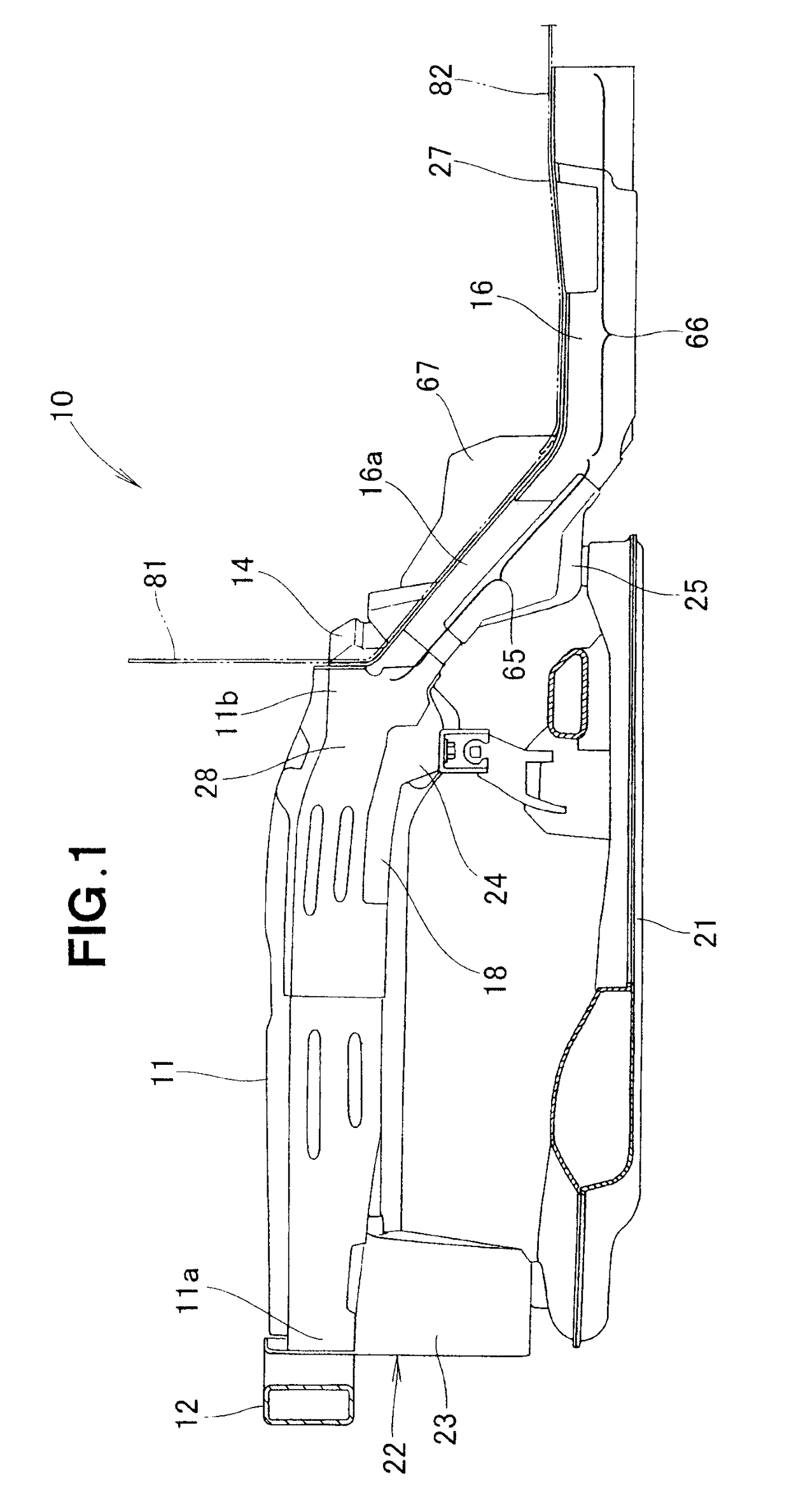
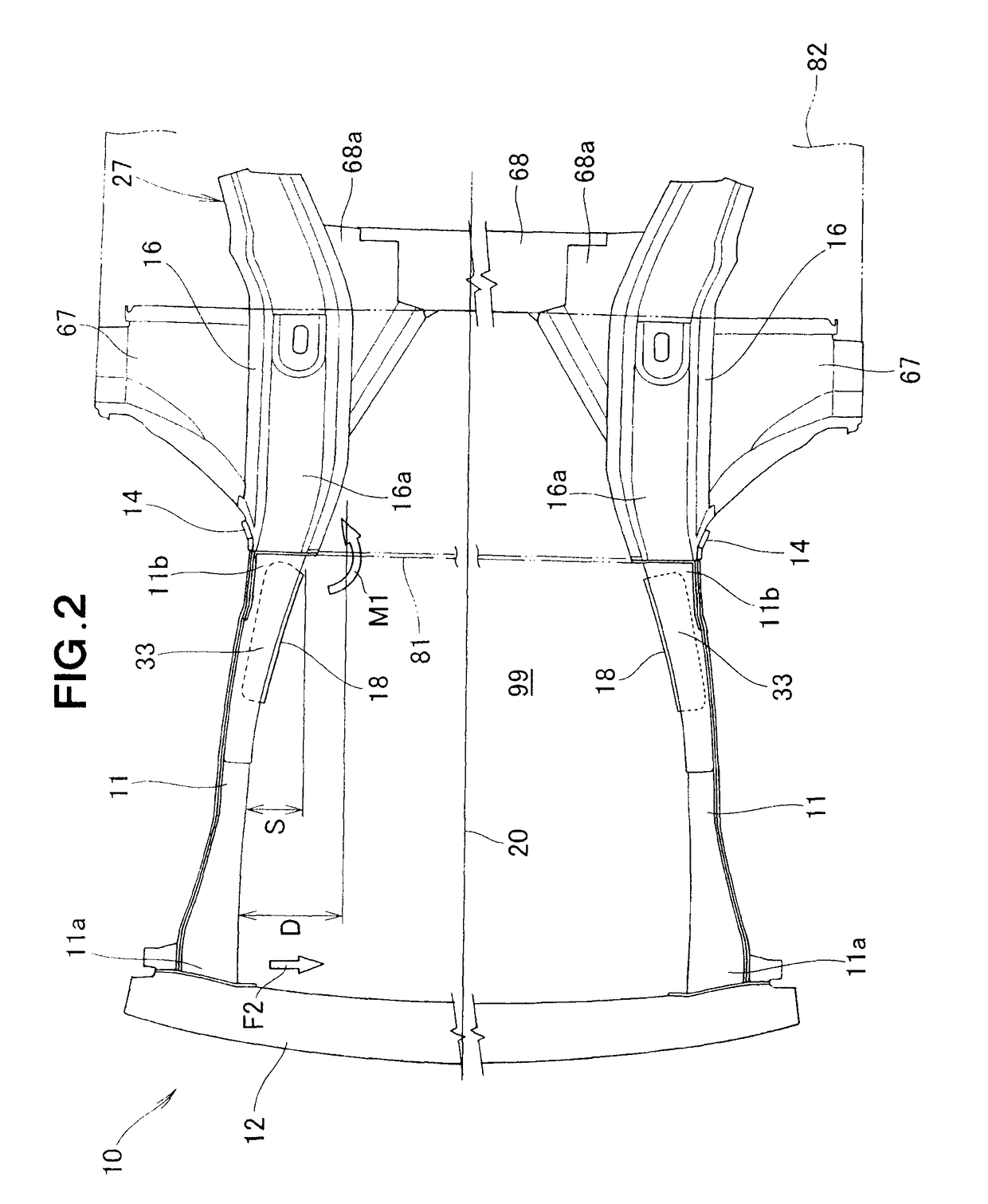
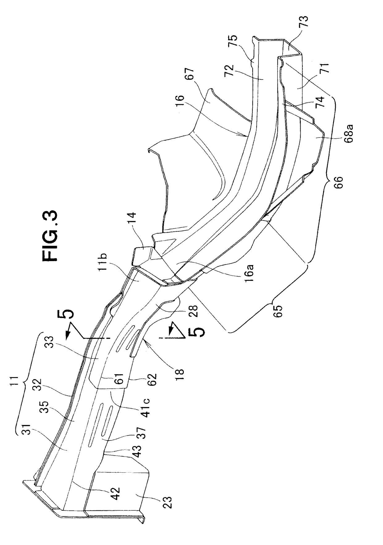
[0027]Referring now to the drawings and FIGS. 1 and 2 in particular, there is shown a vehicle body front part structure 10 according to a preferred embodiment of the present invention. The vehicle body front part structure 10 generally comprises a pair of right and left front side frames 11, 11 extending in a longitudinal direction of the vehicle body, a bumper beam 12 connected to front end portions 11a, 11a of the front side frames 11, 11 and extending in a widthwise direction of the vehicle body, a pair of right and left adapters 14, 14 disposed at rear end portions 11b, 11b of the right and left front side frames 11, 11, respectively, a pair of right and left floor frames 16, 16 connected via the adapters 14, 14 to the rear end portions 11b, 11b of the right and left front side frames 11, 11, respectively, a pair of right and left stiffeners 18, 18 for reinforcing the right and left front side frames 11, 11, respectively, and a sub-frame 21 disposed below the right and left fron...


PUM


Abstract

A vehicle body front part structure having a front side frame including a compressive load bearing frame member extending longitudinally of a vehicle body, and a bending load bearing frame member branched from a longitudinally central portion of the compressive load bearing frame member and curved inwardly toward a longitudinal centerline of the vehicle body as extending rearwardly of the vehicle body. The compressive load bearing frame member has a rear end portion curved inwardly toward the longitudinal centerline of the vehicle body, and reinforcement beads formed on a sidewall of the rear end portion of the compressive load bearing frame member.

Description

FIELD OF THE INVENTION[0001]The present invention relates to a front part structure of an automobile vehicle body including a pair of right and left front side frames each having a compressive load bearing frame member for supporting an axial load acting in a longitudinal direction of the vehicle body.BACKGROUND OF THE INVENTION[0002]Various vehicle body front part structures of the type concerned are known and used heretofore. According to one example shown in Japanese Patent Laid-open Publication (JP-A) No. 2006-290311, a vehicle body front part structure includes a pair of right and left front side frames as main components thereof, and each of the right and left front side frames has an axial load receiving member (hereinafter referred to as “compressive load bearing frame member”) extending in a longitudinal direction of the vehicle body, and a moment receiving member (hereinafter referred to as “bending load bearing frame member”) curved inwardly of the vehicle body as extendi...

Claims


Application Information

Patent Timeline
Patent Type & Authority Patents(United States)
IPC IPC(8): B62D23/00
CPCB62D21/152B62D25/082
Inventor KIHARA, MAKOTOYASUHARA, SHIGETOYOSHIKAWA, SHINICHI
Owner HONDA MOTOR CO LTD
Why Eureka
Try Eureka