Steam generator pipe, associated production method and continuous steam generator

a technology of steam generator and pipe, which is applied in the direction of machines/engines, speed sensing governors, light and heating equipment, etc., can solve the problems of comparatively expensive production, inadequate cooling, adverse heat transfer behavior of steam generator pipes, etc., and achieve the effect of high chrome conten

Inactive Publication Date: 2012-02-28
SIEMENS AG
View PDF28 Cites 8 Cited by
  • Summary
  • Abstract
  • Description
  • Claims
  • Application Information

AI Technical Summary

Benefits of technology

[0008]The underlying object of the invention is thus to specify a steam generator pipe of the type mentioned at the start that, with production kept simple and cost effective, and for a wide bandwidth of different operating conditions, exhibits an especially favorable heat transition behavior. In addition a suitable method of production of such a steam generator pipe as well as a continuous steam generator is to be specified which, with higher operational safety and a high-level of efficiency, possesses an especially simple construction.

Problems solved by technology

The heat transfer behavior of a steam generator pipe can be adversely affected in conventional steam generators which are operated at sub-critical pressures, by the occurrence of so-called departures from nucleate boiling.
In such cases the wall of the pipe is no longer wetted by liquid flow medium—as a rule water—and is thus only inadequately cooled.
A disadvantage of the known steam generator pipes is that they are comparatively expensive to produce as a result of the limited plasticity of the pipe material.
With highly heat-resistant steels in particular with a high chrome content the plasticity is greatly restricted.
The material-related restrictions mean in practice that it is no longer possible, or only possible at great expense, to create internally-ribbed pipes with the desired rib profiles advantageous for flow within the pipe from smooth pipes within the context of a deformation process.
In particular sufficiently steep edge angles and sharp-edged transitions in conjunction with large rib heights can only be produced with difficulty or not at all.
In addition the height of the ribs can only be produced within a narrow frame.
However the one aspect common to all the pipe inserts known to date is that on the one hand they block up the (originally) free cross-section in the center of the pipe and thus lead to very high pressure loss, and that on the other hand they impart a pronounced redirection to the entire flow and thereby in some cases “overswirl” it.
A simple twisted tape for example leads with higher steam content in the two-phase flow to a collection of the water phase in the gusset between the pipe wall and the tape with simultaneous drying out and thereby inadequate cooling down of the inner wall areas on the lee side of the tape, where the lee side refers to the side of the tape that is the steam averted side in the direction of the steam flow.
Steam generator pipes with inserts of the twisted tape type are thus not equally suited to all operating conditions usually occurring with steam generators.

Method used


Image

  • Steam generator pipe, associated production method and continuous steam generator
  • Steam generator pipe, associated production method and continuous steam generator
  • Steam generator pipe, associated production method and continuous steam generator

Examples


Embodiment Construction

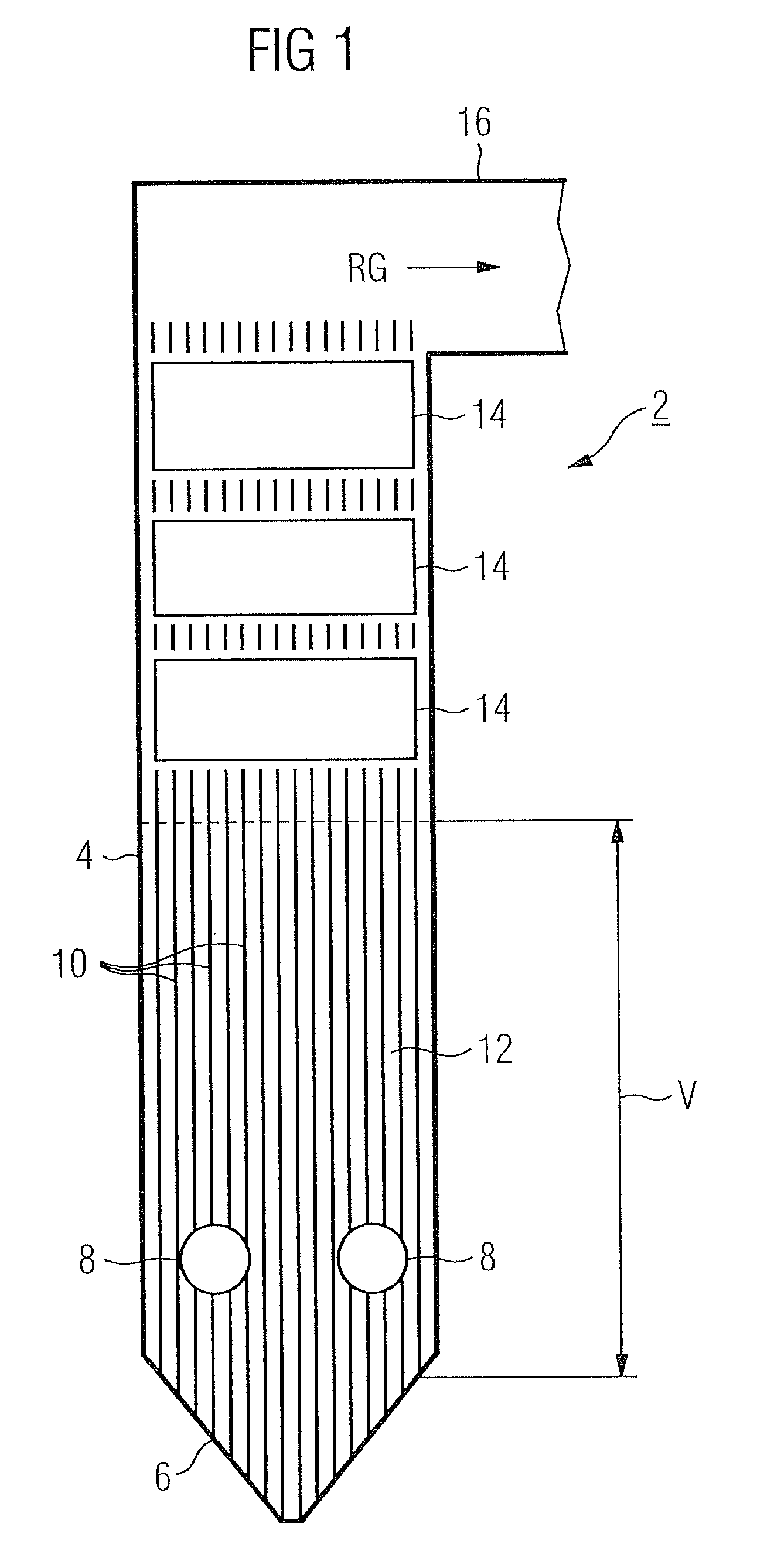
[0030]FIG. 1 shows a schematic diagram of a continuous steam generator 2 with a rectangular cross-section, of which the vertical gas draught is embodied by a surrounding wall- or combustion chamber wall 4 which transforms at its lower end into a funnel-shaped floor 6.

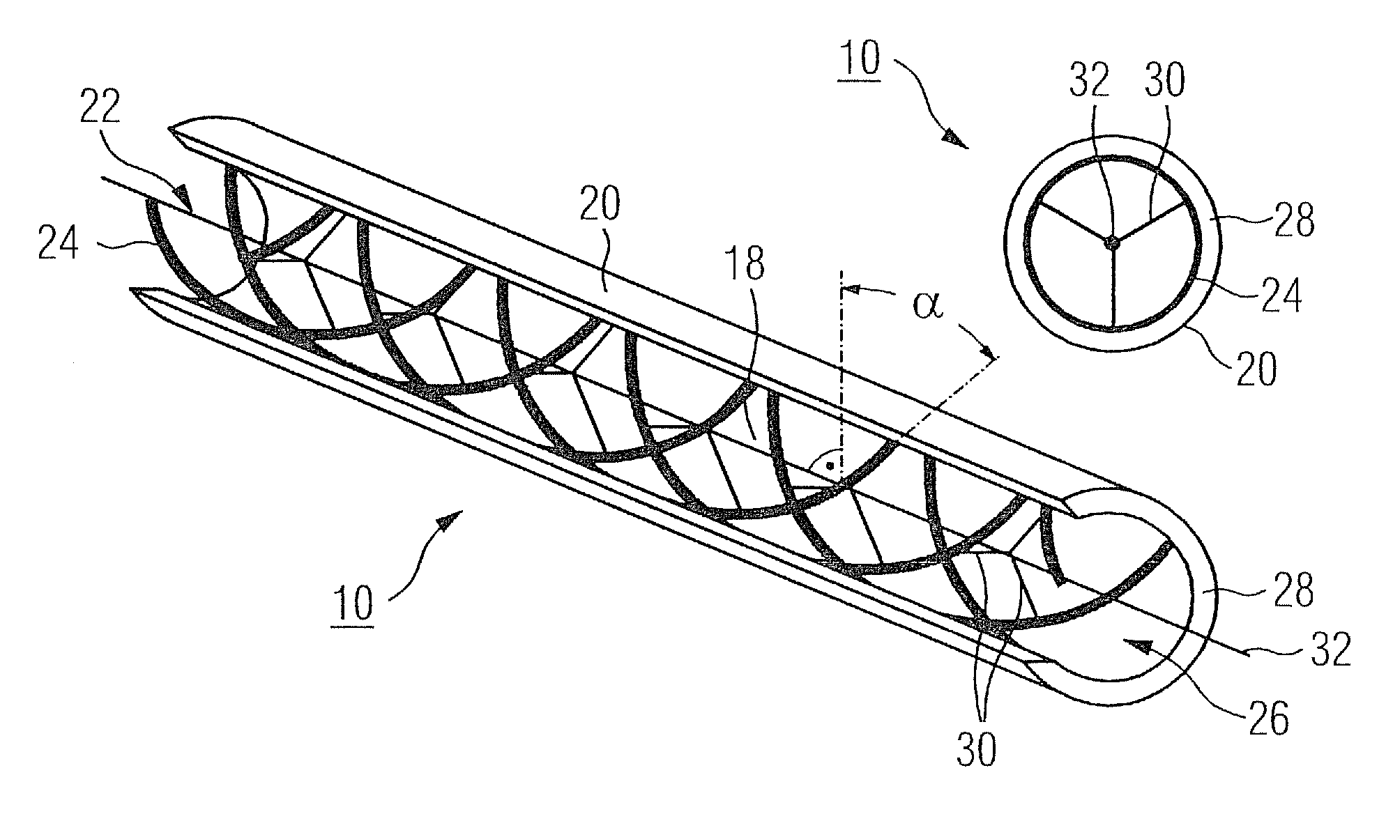
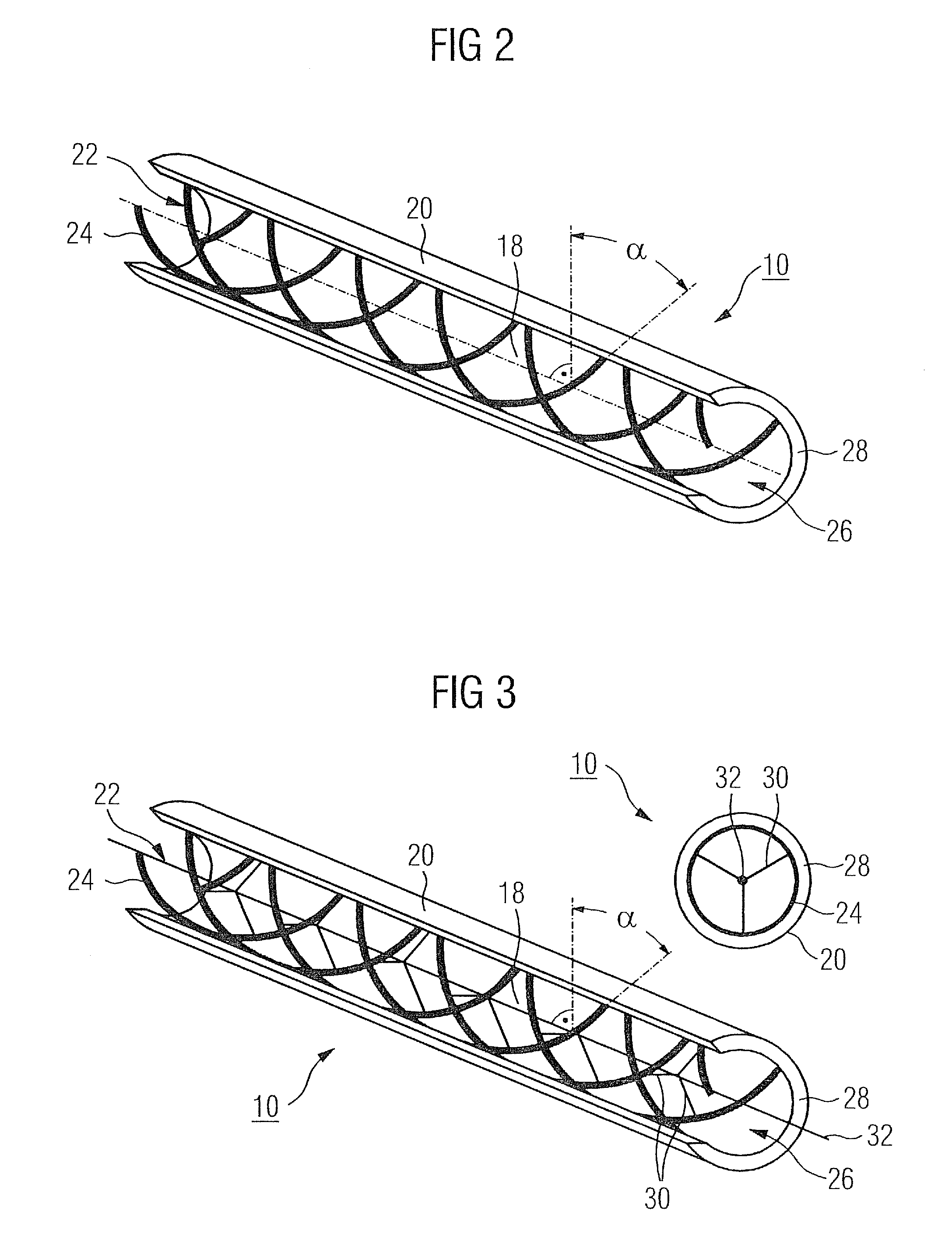
[0031]In a firing area V of the gas draught a number of burners for a fuel are each accommodated in an opening 8, of which only two are visible in the combustion chamber wall 4 made up of steam generator pipes 10. The vertically arranged steam generator pipes 10 are welded together in a gas-tight manner in the firing area V to form a continuous evaporating heating surface 12.

[0032]Above the firing area V of the gas draught are located convection heating surfaces 14. Above these is located a flue gas exit duct 16, via which the flue gas RG created by the combustion of a fossil fuel leaves the vertical gas draught. The flow medium flowing in the steam generator pipes 10 is heated up by the radiant heat of the burner flame...


PUM


Abstract

Disclosed is a steam generator pipe which can be produced in a simple and economical manner and which has a particularly good heat transitional behavior having a large band width with various operational conditions. According to the invention, at least one insert is arranged in the inner chamber of the pipe in order to form a swirl-generating inner profile. The insert comprises a plurality of wires which wind, in a screw-like manner, along the inner wall of the pipe in the form of a multi-path thread.

Description

CROSS REFERENCE TO RELATED APPLICATIONS[0001]This application is the US National Stage of International Application No., PCT / EP2006 / 068757, filed Nov. 22, 2006 and claims the benefit thereof. The International Application claims the benefits of European application No. 05026487.8 filed Dec. 5, 2005, both of the applications are incorporated by reference herein in their entirety.FIELD OF INVENTION[0002]The invention relates to a steam generator pipe with a swirl-generating internal profile. It further relates to a continuous steam generator with these types of steam generator pipes. The invention further relates to a method for producing a steam generator pipe provided with a swirl-generating inner profile.BACKGROUND OF THE INVENTION[0003]Steam generator pipes, usually welded to each other in a gas-tight manner via stays for forming a gas draught surrounding the firing chamber are used in the combustion chamber walls of a continuous steam generator, with said pipes being connected in...

Claims


Application Information

Patent Timeline
Patent Type & Authority Patents(United States)
IPC IPC(8): F28F1/40
CPCF22B37/18F22B29/06
Inventor FRANKE, JOACHIMHERBST, OLIVERSCHMIDT, HOLGER
Owner SIEMENS AG
Why Eureka
Try Eureka