Ball spline device

a technology of spline and ball, which is applied in the direction of bearings, shafts and bearings, bearings, etc., can solve the problems of difficult to form the ball and return the holes directly to the nut member, and achieve the effect of simple manufacturing, time and effort for positioning the scooping portion, and low cos

Active Publication Date: 2012-02-28
THK CO LTD
View PDF27 Cites 5 Cited by
  • Summary
  • Abstract
  • Description
  • Claims
  • Application Information

AI Technical Summary

Benefits of technology

[0009]Further, in each of the conventional ball spline devices, the balls are departed from the ball rolling grooves of the spline shaft by the ball scooping portions provided to the retainer. In this case, the balls climb up the scooping portions so as to be lifted directly above the ball rolling grooves, and then enter the direction converting paths. Thus, it is necessary to provide spaces between the nut member and the spline shaft by that much, which also leads to prevention of downsizing of the nut member.
[0011]The present invention has been made in view of the problems described above, and an object thereof is to provide a ball spline device in which the outer diameter of the nut member can be downsized to the maximum while sufficiently performing the original function, and which can keep reliability while being capable of being simply manufactured at lower cost without involving time and effort in assembly.
[0015]Accordingly, an endless circulation path of the ball is formed in a state of being held in contact with the outer peripheral surface of the spline shaft. When the diameter of the spline shaft is the same as those of the conventional ball spline devices each provided with the retainer, it is possible to reduce the outer diameter of the nut member. This enables downsizing of various industrial machines in which ball spline devices are used. From another viewpoint, when the outer diameter of the nut member to be used in the various industrial machines is predetermined, a spline shaft having a larger diameter in comparison with those of the conventional products can be used in the ball spline device of the present invention. As a result, it is possible, in accordance with enhancement in rigidity of the spline shaft, to enhance accuracy in movement of the nut member and to increase torque transmitted, whereby performance of the industrial machines in which the ball spline device is adopted is enhanced.
[0018]In the ball spline device of the present invention, in which the balls are departed from the ball rolling grooves, it is unnecessary to provide the scooping portion for lifting up the balls from the ball rolling groove, and time and effort for positioning the scooping portion with respect to the ball rolling groove are eliminated. Accordingly, the ball spline device of the present invention can be simply manufactured at lower cost. Further, the balls successively climb up the conventional scooping portion, and hence there is a risk of generating deformation and breakage when the balls circulate therein at high speed. However, in the ball spline device of the present invention in which the scooping portion is not provided, there is no risk as described above, and hence it is possible to enhance reliability in moving the nut member with respect to the spline shaft at high speed.

Problems solved by technology

In addition, when the diameter of the ball is small, the diameter of ball returning holes is also small, and hence it is difficult to form the ball returning holes directly to the nut member.

Method used


Image

  • Ball spline device
  • Ball spline device
  • Ball spline device

Examples


Embodiment Construction

[0025]In the following, a ball spline device of the present invention is described in detail with reference to the accompanying drawings.

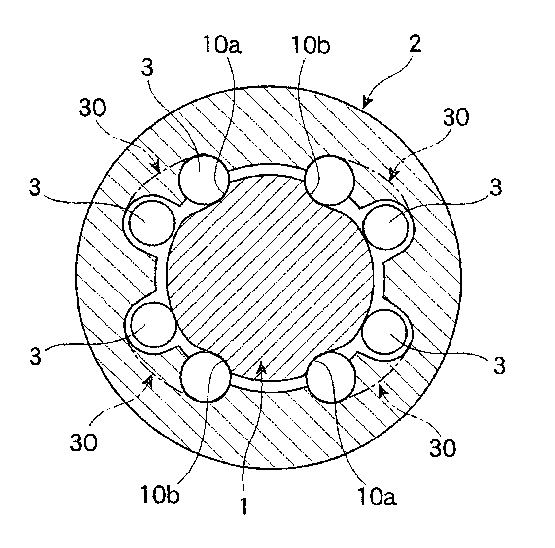
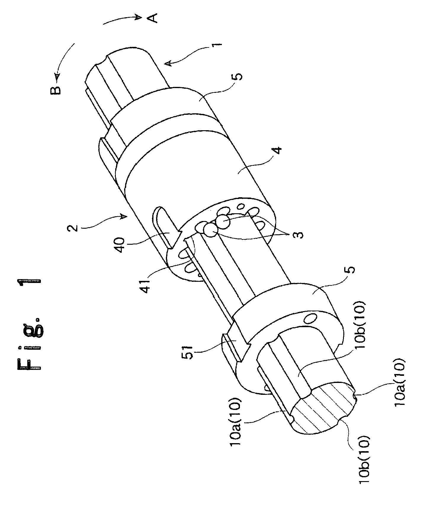
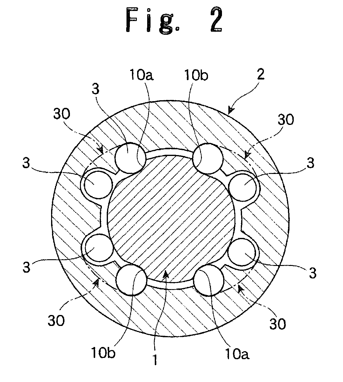
[0026]FIGS. 1 and 2 illustrate an embodiment of the ball spline device to which the present invention is applied. This ball spline device includes a spline shaft 1 formed into a substantially columnar shape in cross section and a nut member 2 formed into a substantially cylindrical shape and assembled to the spline shaft 1 through an intermediation of a large number of balls 3, the nut member 2 freely reciprocating about the spline shaft 1 in the axial direction.

[0027]In the outer peripheral surface of the spline shaft 1, four ball rolling grooves 10 are formed along the axial direction. The balls 3 bear load between the nut member 2 and the spline shaft 1 while rolling in the ball rolling grooves 10. The ball rolling grooves 10 are formed into circular-arc shapes in cross section perpendicular to the longitudinal direction thereof, that is, formed...


PUM


Abstract

Provided is a ball spline device, in which an outer diameter of a nut member can be downsized to the maximum while sufficiently performing an original function, and which can keep reliability while being capable of being simply manufactured at lower cost without involving time and effort in assembly, in which a nut member has a track groove which is formed on an inner peripheral surface facing a spline shaft, the balls circulating in the track groove, the track groove comprises: a linear load groove formed so as to face the ball rolling groove of the spline shaft; a linear non-load groove provided parallel to the linear load groove; and a pair of ball deflection grooves for communicably coupling the linear load groove and the linear non-load groove with each other so as to allow the balls to intercommunicate therebetween, and the ball deflection grooves forcibly change an advancing direction of the balls rolling in the ball rolling groove and cause the balls to depart from the ball rolling groove with use of a profile of the spline shaft.

Description

TECHNICAL FIELD[0001]The present invention relates to a ball spline device, in which a spline shaft and a nut member are combined through an intermediation of a large number of balls so as to be capable of making relatively linear movement, and which is used for linear guide portions of working machines and various industrial machines, and as torque transmission portions of industrial robots.BACKGROUND ART[0002]Conventionally, examples of the ball spline devices of those types include one disclosed in JP 61-179414 U, one disclosed in JP 58-137616 A, and the like. Each of those ball spline devices includes a spline shaft provided with multiple ball rolling grooves extending in the axial direction thereof, and a nut member assembled to the spline shaft through an intermediation of a large number of balls and provided with endless circulation paths of the balls. In accordance with endless circulation of the balls, the nut member can freely move about the spline shaft along the longitud...

Claims


Application Information

Patent Timeline
Patent Type & Authority Patents(United States)
IPC IPC(8): F16C29/06
CPCF16D3/065F16C29/0695F16D3/06F16C29/06
Inventor SHIRAI, TAKEKI
Owner THK CO LTD
Why Eureka
Try Eureka