

Heat-assisted magnetic recording head including plasmon generator
a technology of magnetic recording head and plasmon generator, which is applied in the field of heat-assisted magnetic recording head, can solve the problems of increasing the coercivity of the magnetic recording medium, reducing the thermal stability of the magnetization of the magnetic fine particles, and difficult to perform data writing with the existing magnetic recording head
- Summary
- Abstract
- Description
- Claims
- Application Information
AI Technical Summary
Benefits of technology
Problems solved by technology
Method used
Image

Examples
first embodiment
[0061]Preferred embodiments of the present invention will now be described in detail with reference to the drawings. First, reference is made to FIG. 6 to describe a magnetic disk drive as a magnetic recording device according to a first embodiment of the invention. As shown in FIG. 6, the magnetic disk drive includes a plurality of magnetic disks 201 as a plurality of magnetic recording media, and a spindle motor 202 for rotating the plurality of magnetic disks 201. The magnetic disks 201 of the present embodiment are for use in perpendicular magnetic recording. Each magnetic disk 201 has such a structure that a soft magnetic backing layer, a middle layer, and a magnetic recording layer (perpendicular magnetization layer) are stacked in this order on a disk substrate.
[0062]The magnetic disk drive further includes an assembly carriage device 210 having a plurality of driving arms 211, and a plurality of head gimbal assemblies 212 attached to respective distal ends of the driving arm...
modification examples
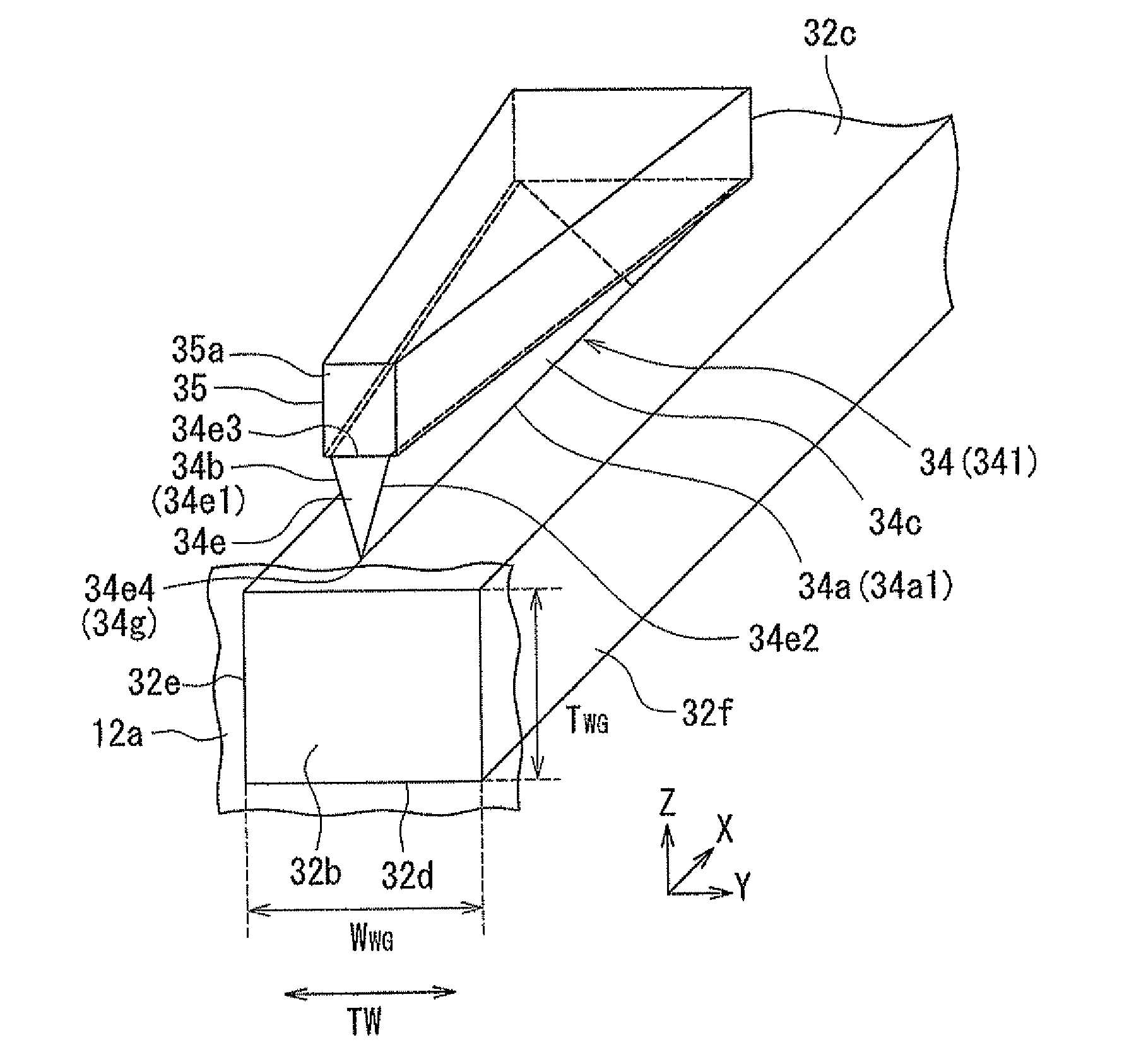
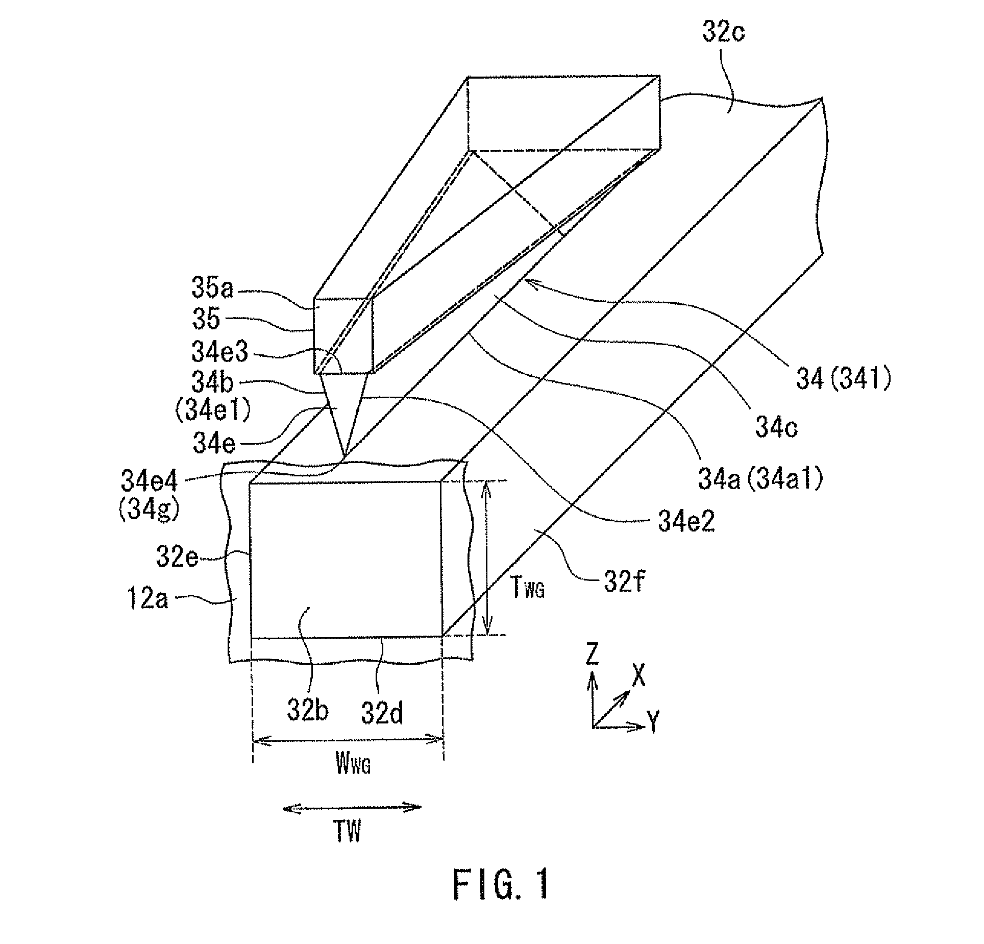
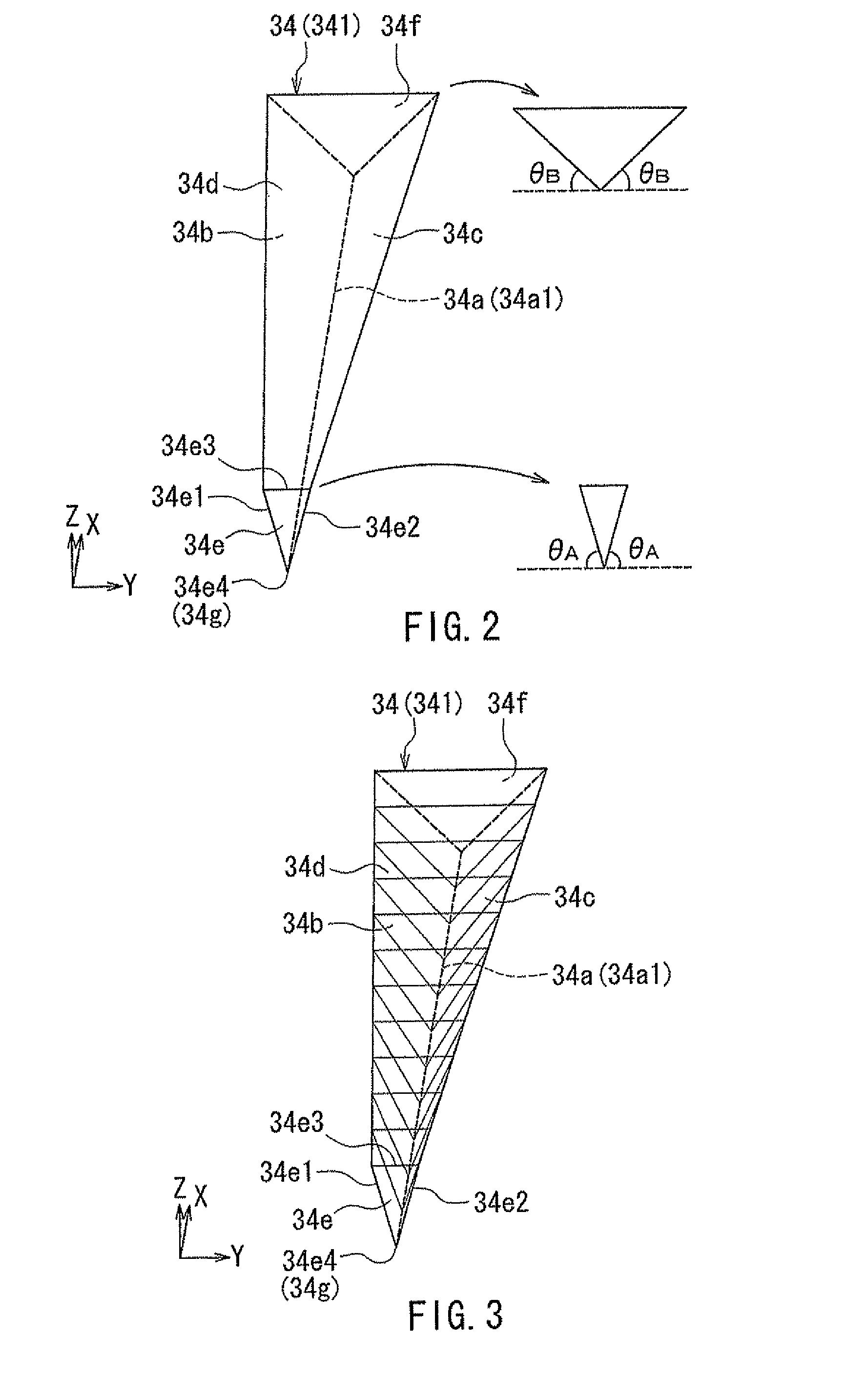
[0128]A first modification example of the present embodiment will now be described with reference to FIG. 17 and FIG. 18. FIG. 17 is a perspective view showing the plasmon generator of the first modification example. FIG. 18 is an explanatory diagram showing the shapes of a plurality of cross sections of the plasmon generator shown in FIG. 17 at respective different distances from the medium facing surface 12a. The plasmon generator 34 of the first modification example includes a first portion 134A that has an end face located in the medium facing surface 12a, and a second portion 134B that is located farther from the medium facing surface 12a than is the first portion 134A so as to be continuous with the first portion 134A.
[0129]The first portion 134A has the shape of a triangular prism. The cross section of the first portion 134A parallel to the medium facing surface 12a has the shape of a triangle with the vertex downward. The end of the second portion 134B at the position of the...
second embodiment
[0169]A second embodiment of the present invention will now be described with reference to FIG. 27 and FIG. 28. FIG. 27 is a perspective view showing the plasmon generator of the heat-assisted magnetic recording head according to the present embodiment. FIG. 28 is an explanatory diagram showing the shapes of a plurality of cross sections of the plasmon generator shown in FIG. 27 at respective different distances from the medium facing surface.
[0170]The plasmon generator 34 of the present embodiment has the first portion 134A, the second portion 134B, and the third portion 134C, as does the plasmon generator 34 of the second modification example of the first embodiment shown in FIG. 19 and FIG. 20.
[0171]In the present embodiment, each of the inclined surfaces 142a and 143a included in the first portion 134A forms a constant angle of inclination with respect to the evanescent light generating surface 32c regardless of the distance from the medium facing surface 12a. Consequently, in t...
PUM
| Property | Measurement | Unit |
|---|---|---|
| angle | aaaaa | aaaaa |
| wavelength | aaaaa | aaaaa |
| emittable wavelength range | aaaaa | aaaaa |
Abstract
Description
Claims
Application Information