Reinforcing bar binding machine

a technology of reinforcing bars and binding machines, which is applied in the direction of other domestic articles, manufacturing tools, manufacturing equipment/tools, etc., can solve the problems of excessively large curl diameter, excessive small diameter of wire fed out from the guide part, and troublesome dimensional control, etc., and achieve high accuracy

Active Publication Date: 2012-03-06
MAX CO LTD
View PDF11 Cites 20 Cited by
  • Summary
  • Abstract
  • Description
  • Claims
  • Application Information

AI Technical Summary

Benefits of technology

[0010]One or more embodiments of the present invention provide a reinforcing bar binding machine which can curl a wire with high accuracy.
[0013]Thus, the first to third guide pins have simple shapes, so that dimensional variations thereof are easily suppressed, and the dimensional accuracy is determined by only the attaching positions of the first to third guide pins to the guide part, so that accuracy can be easily obtained. Therefore, the first to third guide pins with which the wire comes into contact are provided at correct positions, the wire is correctly curled, and the curl diameter becomes steady. Further, the first to third guide pins have simple shapes, so that a material with high hardness can be freely selected for the guide pins.
[0017]In the above configuration, the first guide pin, the second guide pin, and the third guide pin are made of a material with high hardness such as carbide pins and ceramic pins, so that these guide pins are hardly worn, and portions which come into contact with the wire and are easily worn of the wire guide tube, the wire cutting mechanism, and the curl guide are not directly contacted by the wire, so that their durability can be greatly improved. Further, the material with high hardness can be acquired comparatively inexpensively if the material has a pin shape, so that the cost can be reduced to be low.
[0019]In the above configuration, the sectional shapes of the first guide pin, the second guide pin, and the third guide pin are noncircular such as square, rectangular, and oval, so that loosening of the guide pin can be effectively suppressed. In other words, pins having noncircular sectional shapes hardly rotate, so that loosening due to rotation during a long period of use, which easily occurs on guide pins having circular sections attached by fitting and fixing (caulking, etc.) is effectively suppressed.
[0021]In the above configuration, a wearing preventive plate made of a material with high hardness is fitted and fixed to a guide part side wall between the first guide pin and the second guide pin, so that the side wall of the guide part which always comes into contact with the wire when curling the wire is hardly worn, and the wire can be curled normally over a long period of time, and as a result, the durability of the binding machine is improved.
[0023]In the above configuration, the wearing preventive plate is fitted to a concave portion formed on the side wall, and the surface of the wearing preventive plate is pressed and fixed by the tip ends of the first guide pin and the second guide pin, so that the wearing preventive plate can be easily and reliably fixed without a fixing means such as screwing and welding, etc., and the surface of the wearing preventive plate becomes flush with the wall surface of the side wall and makes the wire passage smooth.

Problems solved by technology

However, the above-described configuration has the following problems.
Therefore, these may pose problems that the curl diameter of the wire fed out from the guide part is excessively small and the hooks cannot grasp the wire, or the curl diameter is excessively large and the end portion of the wire returned after being looped cannot enter a curl pickup guide of the guide part.
Therefore, dimensional control is very troublesome and the component cost increases.
Further, the three components which curl the wire are always worn by the iron-made wire, so that they are worn, and in particular, a portion which forms a curl on the wire is greatly worn, and this wearing increases the wire feeding resistance and deteriorates the smoothness of the wire feeding, and during repetition of use, the curling is deteriorated, and the curl diameter of the wire becomes larger, so that for guiding the wire, the components need to be replaced.
It is possible that the components are hardened to cope with the problem of wearing, however, the shapes of the components are complicated, so that selection of the material (hardness) is limited.
In this case, if the next binding operation is performed without knowing the swarf, the next wire jams at the guide part and it is troublesome to take this out.

Method used


Image

  • Reinforcing bar binding machine
  • Reinforcing bar binding machine
  • Reinforcing bar binding machine

Examples


Embodiment Construction

[0033]Exemplary embodiments of the invention are described in reference to drawings.

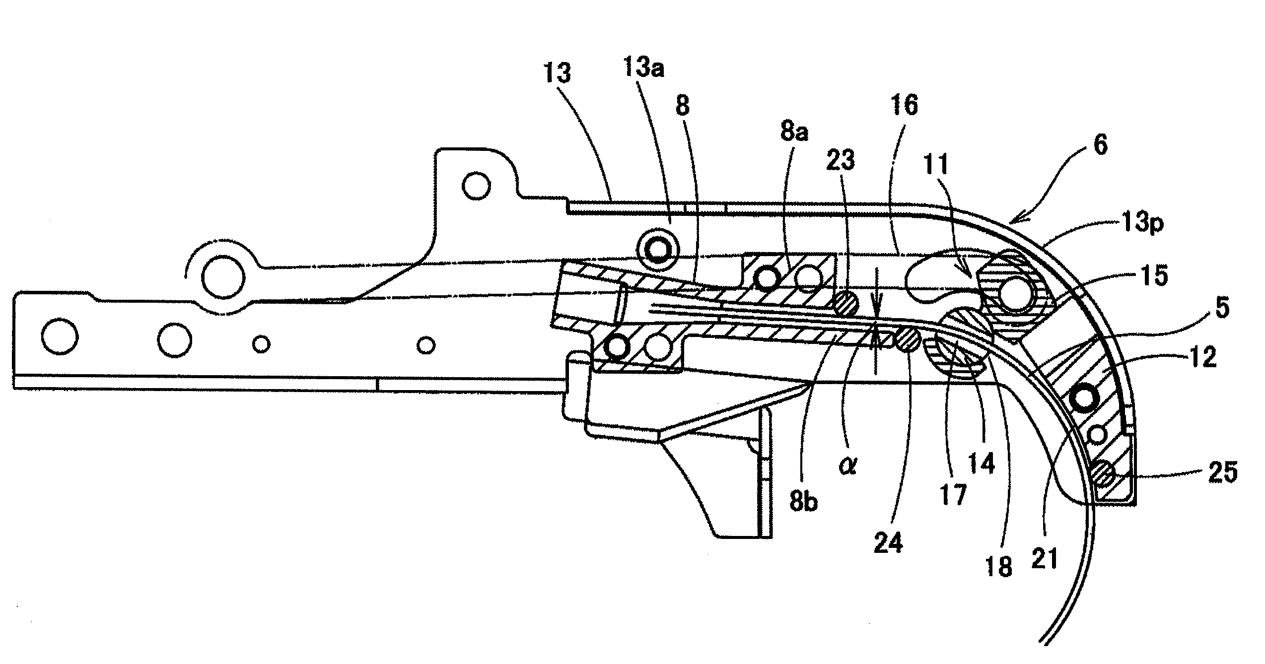
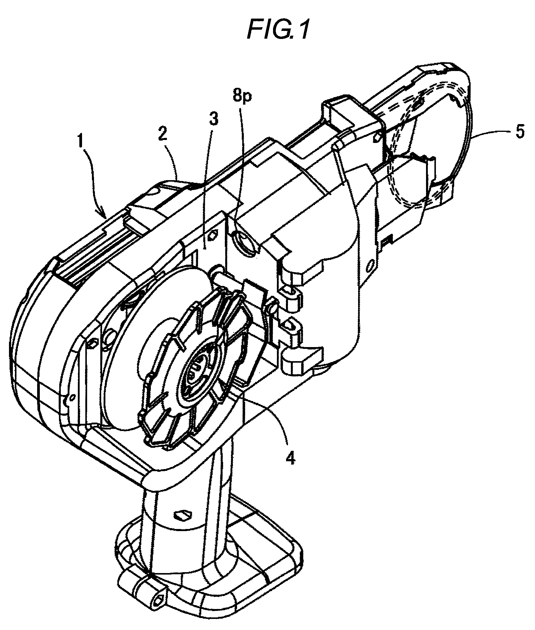
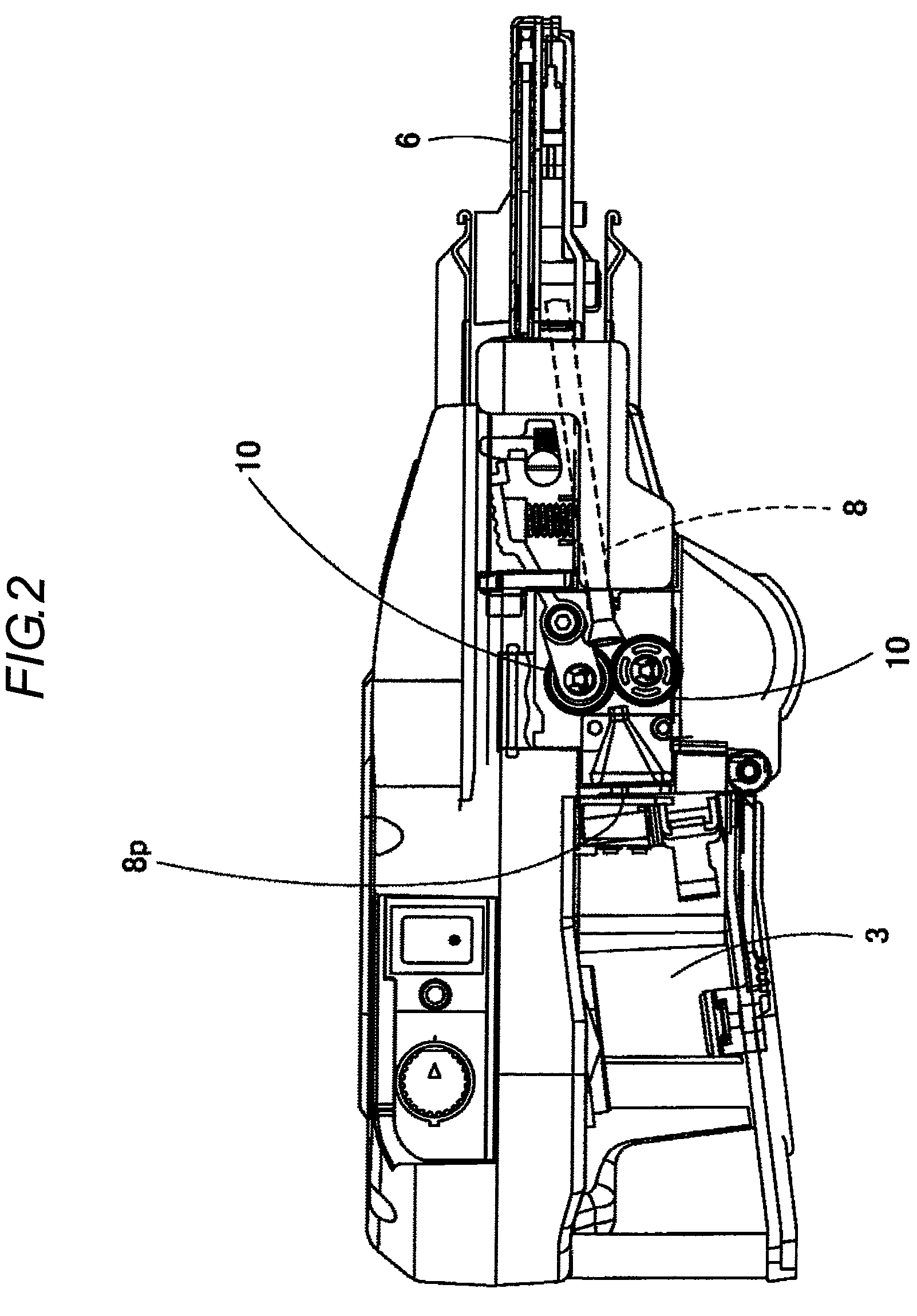
[0034]In FIG. 1 to FIG. 3, the reference numeral 1 denotes a reinforcing bar binding machine. In the reinforcing bar binding machine 1, a wire reel 4 around which a reinforcing bar binding wire 5 is wound is fitted in a housing chamber 3 provided in a binding machine body 2, and the wire 5 is fed to a guide part 6 provided on the tip end of the binding machine body 2 while the wire reel 4 is rotated, and curled by the guide part 6 and fed out to the circumference of reinforcing bars 7 arranged inside the guide part 6 and wound around the reinforcing bars, and then the root side of the wire 5 is cut and the wound portion is twisted to bind the reinforcing bars 7.

[0035]In the binding machine body 2, a guide tube 8 through which the wire 5 pulled out from the wire reel 4 is inserted is provided. One end 8p (see FIG. 1) of the guide tube 8 is opened to the housing chamber 3, and the other end is position...


PUM

PropertyMeasurementUnit
hardnessaaaaaaaaaa
shapesaaaaaaaaaa
circumferenceaaaaaaaaaa

Abstract

A reinforcing bar binding machine is provided with: a guide tube for guiding a wire from a wire reel mounted on a binding machine body; a curl guide; a wire cutting mechanism disposed between the guide tube and the curl guide; a first guide pin that is disposed at an end portion of the guide tube or in a vicinity of the end portion of the guide tube, and guides an outer side surface which is an outer side of a wire curve; a second guide pin that is disposed at the end portion of the guide tube or in a vicinity of the end portion of the guide tube, and guides an inner side surface which is an inner side of the wire curve; and a third guide pin that is disposed inside of the curl guide and guides the outer side surface. The wire is brought into contact with the first guide pin, the second guide pin, and the third guide pin, when the wire is fed around a reinforcing bar.

Description

BACKGROUND OF THE INVENTION[0001]1. Field of the Invention[0002]The present invention relates to a reinforcing bar binding machine in which a wire pulled out from a wire reel is fed to a guide part provided on the tip end of a binding machine body, curled by the guide part and fed out to the circumference of the reinforcing bars arranged inside the guide part, and looped and wound around the reinforcing bars and twisted to bind the reinforcing bars.[0003]2. Background Art[0004]A reinforcing bar binding wire is pulled out from the wire reel, and fed out from a guide part on the binding machine tip end while being curled, and looped and wound around reinforcing bars, and at the guide part, the wire must be curled and fed out. In order to curl the wire, the wire should be bent by at least three points.[0005]That is, the guide part includes three components arranged in order, an end portion of a guide tube which guides feeding of the wire from the wire reel, a wire cutting mechanism for...

Claims


Application Information

Patent Timeline
Patent Type & Authority Patents(United States)
IPC IPC(8): B21F15/04B21F9/02B21F9/00B21F11/00
CPCE04G21/122Y10T29/5103E04G21/123
Inventor KUSAKARI, ICHIRO
Owner MAX CO LTD
Why Eureka
Try Eureka