Solenoid valve control apparatus and actuator
a solenoid valve and actuator technology, applied in the direction of valve housing, operating means/releasing devices, valves, etc., can solve the problems of unbalanced load, abnormal noise, and attraction of solenoid, so as to prevent or suppress the generation of abnormal noise, and prevent the generation of rattle
- Summary
- Abstract
- Description
- Claims
- Application Information
AI Technical Summary
Benefits of technology
Problems solved by technology
Method used
Image

Examples
first embodiment
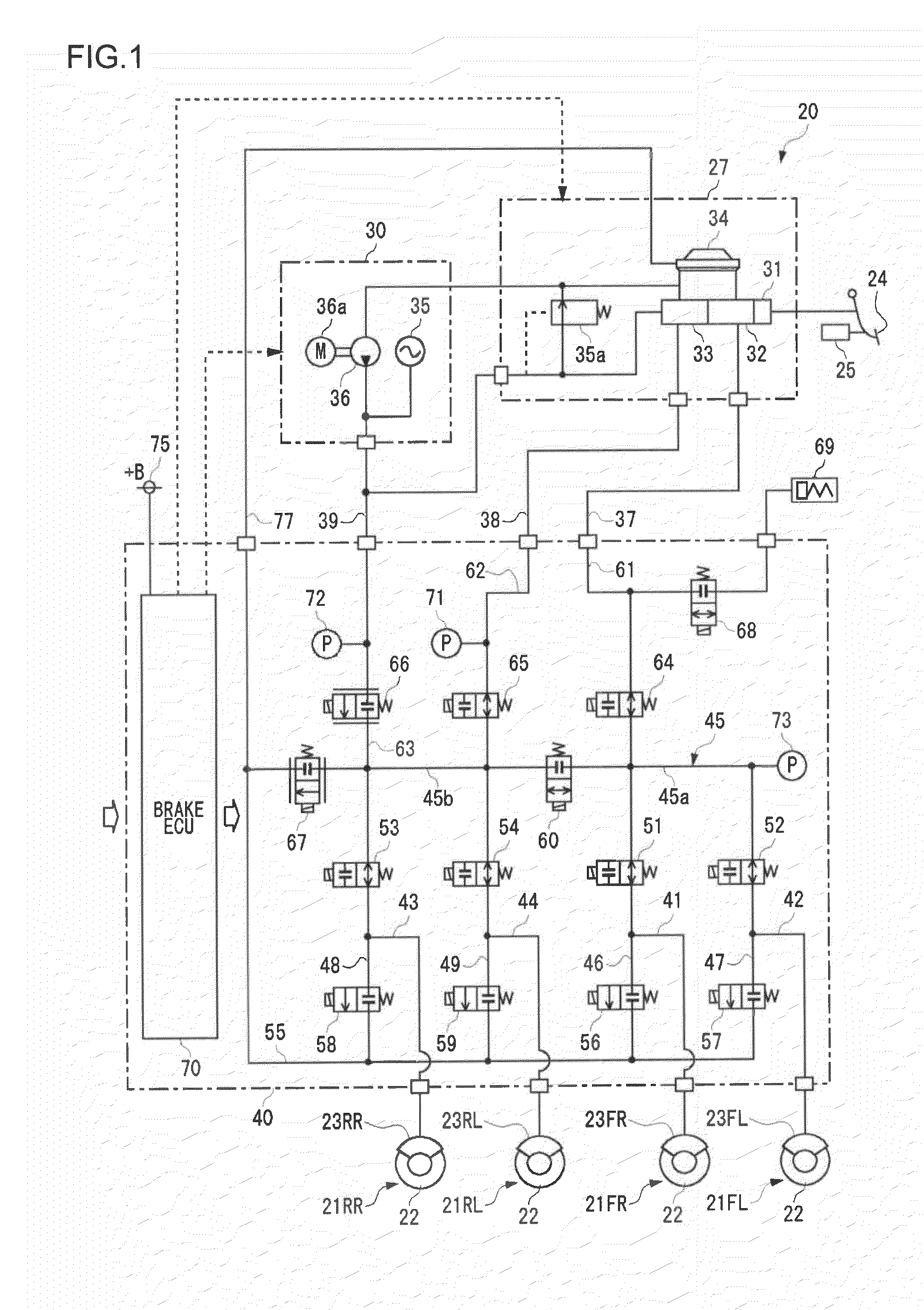
[0039]FIG. 1 is a system diagram of a brake control apparatus according to a first embodiment of the invention.
[0040]A brake control apparatus 20 forms an electronically-controlled brake system for a vehicle, and controls braking forces that are applied to four wheels of a vehicle. The brake control apparatus 20 is mounted on a hybrid vehicle that includes an electric motor and an internal combustion engine as a travel driving source. In this hybrid vehicle, regenerative braking control for braking a vehicle by regenerating the kinetic energy of the vehicle as electrical energy and hydraulic braking control using the brake control apparatus 20 may be executed for the braking of the vehicle. The vehicle of the present embodiment performs a brake regeneration cooperative control that generates a desired braking force by the combination of the regenerative braking control and the hydraulic braking control.
[0041]The brake control apparatus 20 includes disc brake units 21FR, 21FL, 21RR, ...
second embodiment
[0105]A second embodiment of the invention will be described below. The present embodiment is substantially the same as the first embodiment except that the control of the supply of current supplied to the hydraulic control valve 101 of the present embodiment is slightly different from that of the first embodiment. Accordingly, the description of the structure and processing common to the first embodiment will not be repeated appropriately.
[0106]FIG. 9 is a timing diagram illustrating a method for controlling current supplied to a solenoid 103 of a second embodiment. FIG. 9 corresponds to FIG. 7A. A broken line of FIG. 9 illustrates target hydraulic pressure (target wheel cylinder pressure), and a solid line illustrates target current to be supplied to a hydraulic control valve 101. A horizontal axis indicates the passage of time.
[0107]Like in the first embodiment, at least constant bias current is secured during the driving of the hydraulic control valve 101 in the present embodime...
third embodiment
[0108]A third embodiment of the invention will be described below. The present embodiment is to prevent the generation of an abnormal noise by the structure of a hydraulic control valve. Accordingly, the control method of the first or second embodiment does not need to be used necessarily.
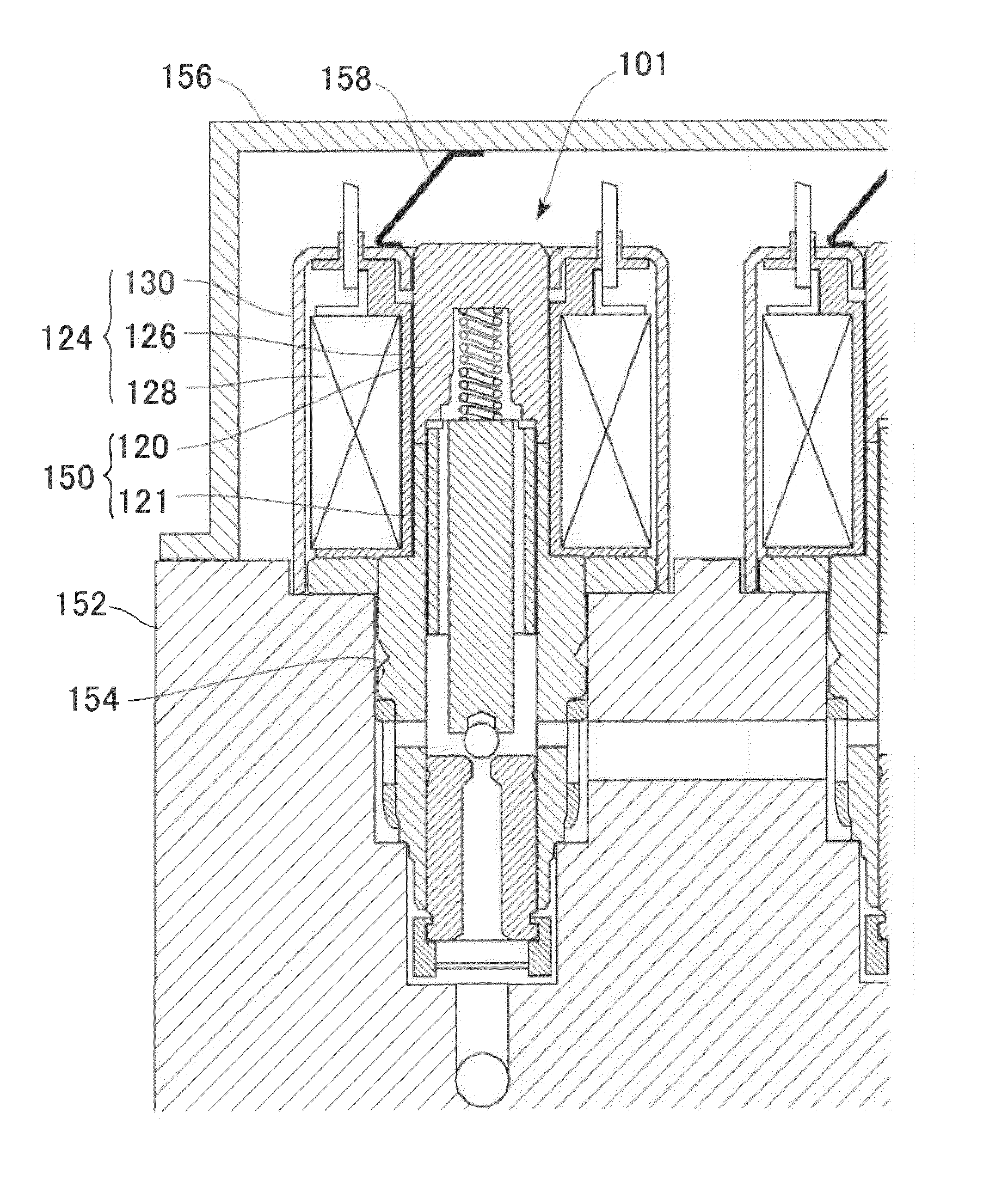
[0109]FIGS. 10A and 10B are views illustrating the structure of main parts of a hydraulic control valve according to a third embodiment. FIG. 10A is a view illustrating the hydraulic control valve to which current is not supplied, and FIG. 10B is a view illustrating the hydraulic control valve to which current is supplied.
[0110]In the hydraulic control valve of the present embodiment, a valve main body is fixed to an actuator block 152 while being inclined so that an inner peripheral surface of a coil unit 124 to be inclined by a biasing force of a leaf spring 158 is substantially parallel to an outer peripheral surface of a solenoid part 150. That is, as described above, a concentrated load is app...
PUM
 Abstract
Description
Claims
Application Information
 - R&D
- Intellectual Property
- Life Sciences
- Materials
- Tech Scout
- Unparalleled Data Quality
- Higher Quality Content
- 60% Fewer Hallucinations
Browse by: Latest US Patents, China's latest patents, Technical Efficacy Thesaurus, Application Domain, Technology Topic, Popular Technical Reports.
© 2025 PatSnap. All rights reserved.Legal|Privacy policy|Modern Slavery Act Transparency Statement|Sitemap|About US| Contact US: help@patsnap.com