Wave and wind power generation

a technology of wind power generation and wave power, which is applied in the direction of floating buildings, vessel safety, and vessel movement reduction by mass displacement, can solve the problems of small lift component, inability to produce positive torque, and limited conditions over which a fixed blade wells turbine operates with reasonable efficiency, etc., to achieve the effect of reducing disadvantages and increasing power generation efficiency

Inactive Publication Date: 2012-03-06
ITI SCOTLAND
View PDF12 Cites 26 Cited by
  • Summary
  • Abstract
  • Description
  • Claims
  • Application Information

AI Technical Summary

Benefits of technology

[0012]The present invention attempts to reduce the disadvantages associated with the above-discussed arrangements by providing a floatable platform which is stabilized relat...

Problems solved by technology

Moreover, during lulls in the sea or when the air velocity drops to zero during twice-per-wave flow reversal, the Wells turbine needs little power to stay rotating.
Simpler Wells turbines employ a set of fixed pitch blades and whilst these provide a generally very positive contribution to the creation of electrical energy the range of wave, and therefore airflow, conditions over which a fixed blade Wells turbine operates with reasonable efficiency is severely limited by blade stall.
Below 2 degrees, in the low air velocity operating area, the lift component is too small to produce positive torque and the rotor tends to lose speed.
The rapidly increasing drag forces dominate the less rapidly declining lift forces and efficiency is compromised.
Whilst such turbines are relatively efficient and are able to extract large amounts of energy from the wind, the higher efficiency turbines tend to have very large diameter blades and hence require very high platforms or towers upon which they can be safely mounted.
On land this does not present a problem as the tower can be firmly secured to ground but the security of fixture is somewhat more problematic when mounted to a floating platform which is subjected to the motion of the waves.
Any such motion causes the turbine to oscillate from a steady state condition and creates what can be adverse structural loadings on both the turbine and the support tower itself.
Whilst this additional energy extraction can be advantageous it has to be balanced against the structural loading on the support...

Method used


Image

  • Wave and wind power generation
  • Wave and wind power generation
  • Wave and wind power generation

Examples


Embodiment Construction

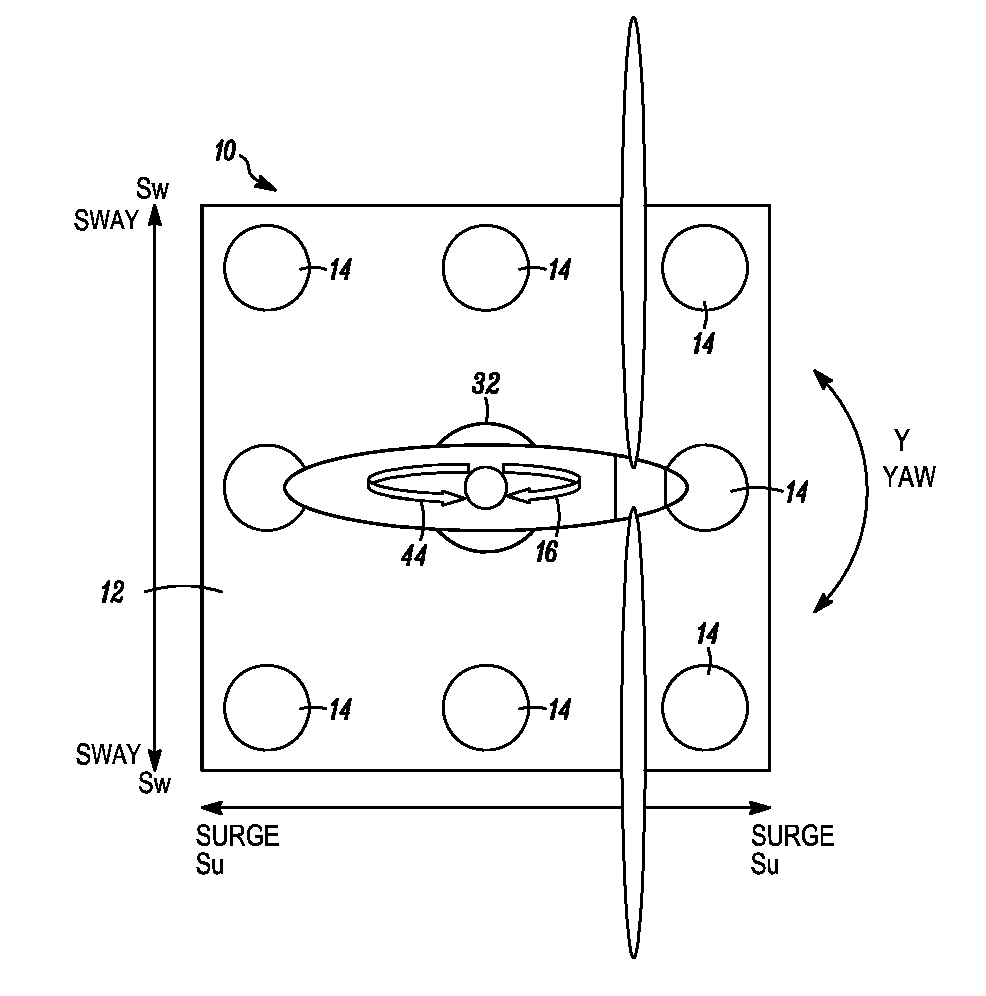
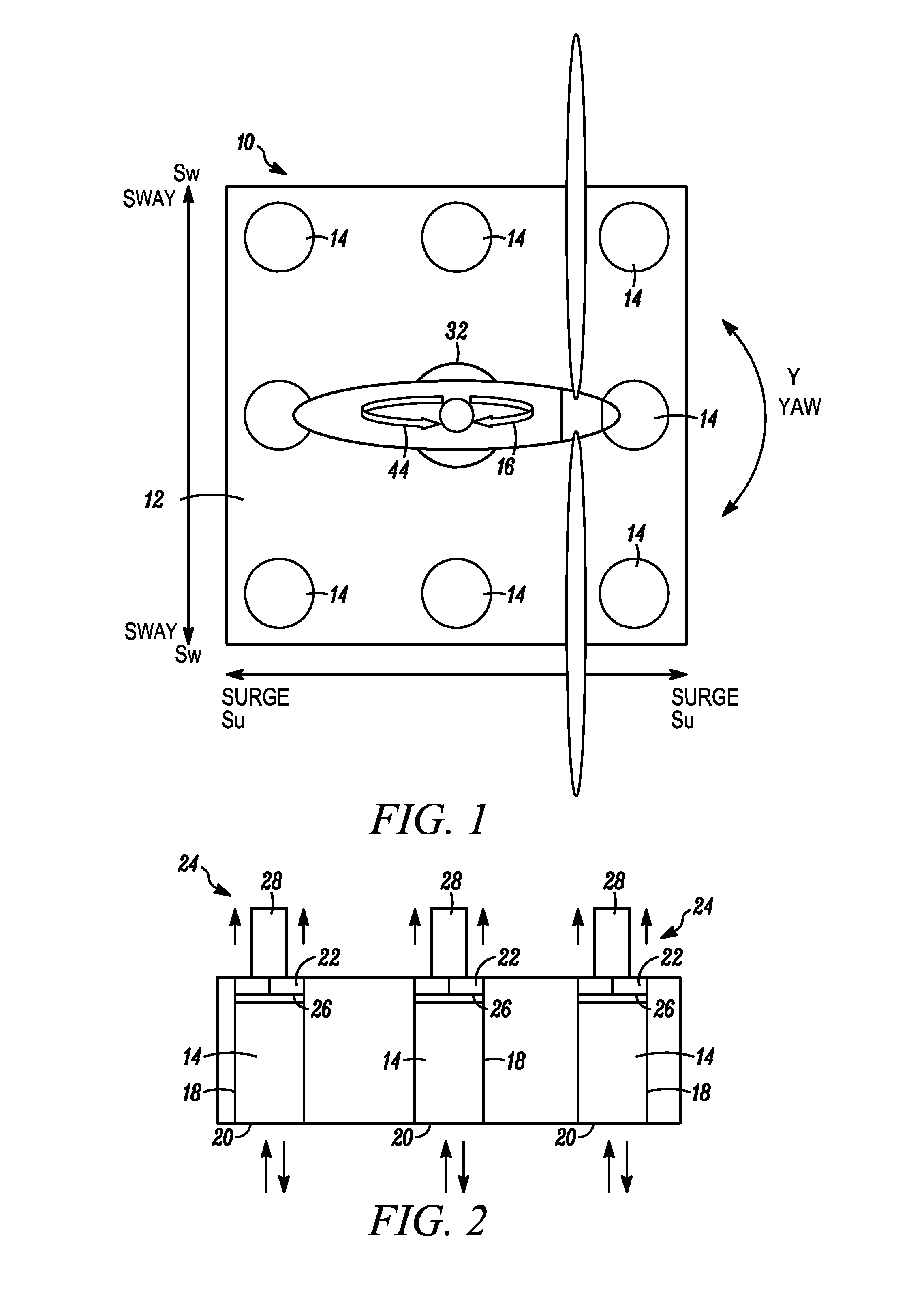
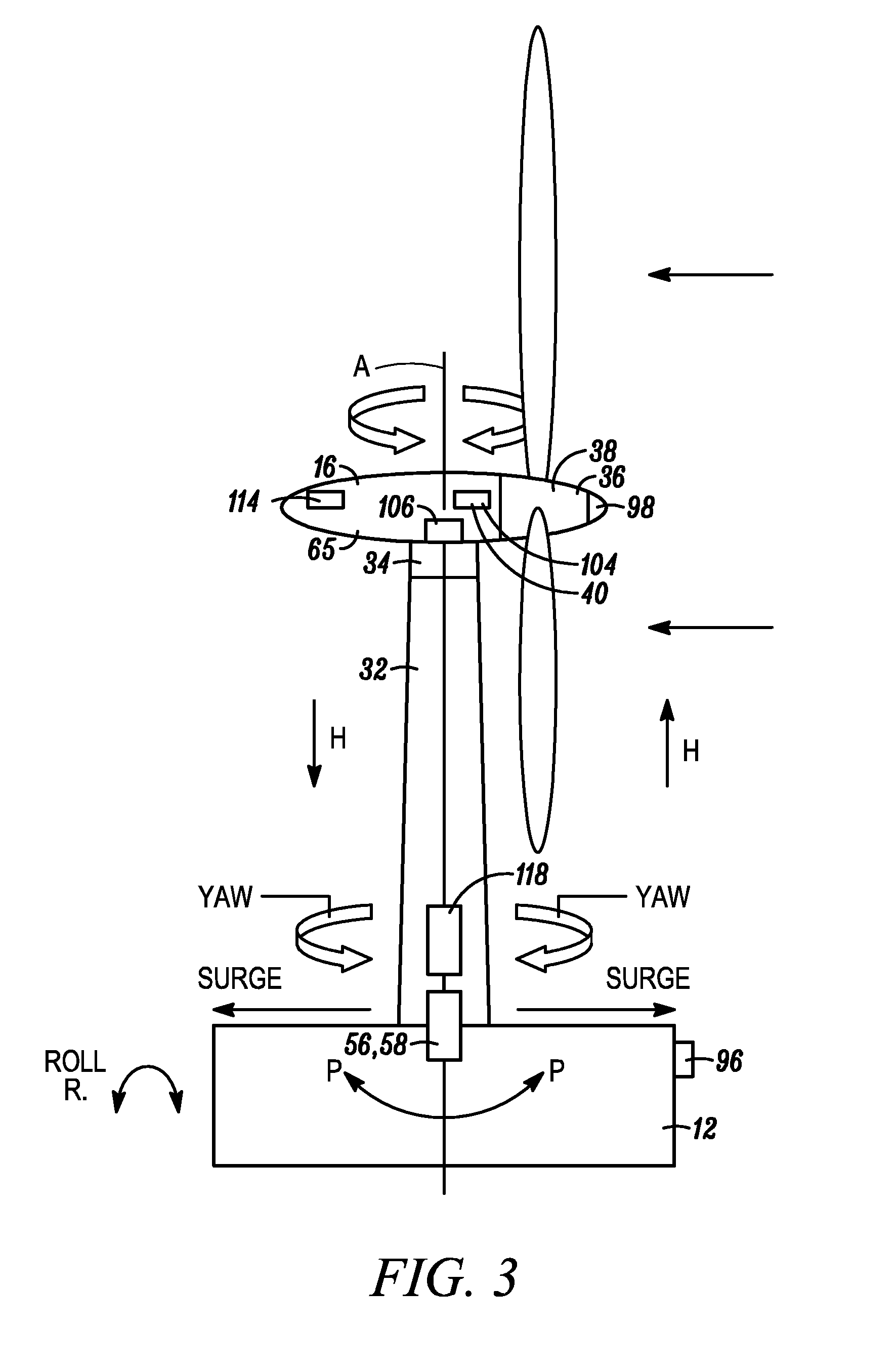
[0042]Referring now to the drawings in general but particularly to FIG. 1, it will be appreciated that a platform 10 according to the present invention comprises a base 12 within which may be provided a plurality of oscillating water columns (OWC's) shown diagrammatically at 14 and upon which may be provided a wind turbine shown generally at 16 and being rotatable about axis A. In various arrangements one or more or both of the OWC's and wind turbine may be provided. When floating on water and exposed to the motion of the waves and other influences the platform can move about three axis in one or more of six ways (pitch, roll, yaw, sway, surge and heave), all of which are discussed in detail later herein but each of which are marked with appropriate arrows (P, R, Y, Sw, Su and H) throughout the drawings. The OWC's may be provided in the singular, matched pairs at opposite extremities of the platform or in multiples thereof positioned at appropriate positions within the platform depe...


PUM


Abstract

A wave and wind power generation system including a platform and one or more oscillating water columns (OWC's). Included is an airflow control mechanism, a controller and a motion sensor for detecting motion of the platform. Additionally, the controller controls the airflow control mechanism so as to at least partially arrest undesirable motion of the platform.

Description

[0001]This application is the U.S. national phase of International Application No. PCT / GB2007 / 050603 filed 2 Oct. 2007 which designated the U.S. and claims priority to British Patent Application No. 0620038.0 filed 10 Oct. 2006, the entire contents of each of which are hereby incorporated by reference.BACKGROUND OF THE INVENTION[0002]1. Field of the Invention[0003]The present invention relates to floating power generation systems and relates particularly but not exclusively to such systems having stabilization control.[0004]2. Discussion of Prior Art[0005]Offshore power generation which harnesses the power of the waves has the potential to become a major source of energy and has been the subject of much experimentation and development over the past forty or more years. Such systems harness the power of the waves either directly or indirectly and convert that energy into electricity which is then transported to shore for subsequent use. The oscillating water column (OWC) has become a...

Claims


Application Information

Patent Timeline
IPC IPC(8): F03D9/00
CPCB63B39/02F03B13/142F03D9/00F03B13/00B63B35/44B63B2035/446B63B2035/4466Y02E10/72Y02E10/32Y02E10/38F05B2240/93F03D13/25Y02E10/727F03D9/25Y02E10/30F03D13/20B63B35/00B63B43/04
Inventor EDWARDS, JAMES IANDIVER, PETER THOMAS
Owner ITI SCOTLAND
Why Eureka
Try Eureka