X-ray CT system having a patient-surrounding, rotatable anode with an oppositely rotatable x-ray focus

a ct system and patient-centered technology, applied in tomography, applications, instruments, etc., can solve the problems of limited power that can be achieved with the x-ray tube at relatively low tube power, limit has been reached for the third generation of computed tomography apparatus, etc., and achieve the effect of increasing x-ray power

Inactive Publication Date: 2012-03-06
SIEMENS AG
View PDF18 Cites 6 Cited by
  • Summary
  • Abstract
  • Description
  • Claims
  • Application Information

AI Technical Summary

Benefits of technology

[0010]An object of the present invention is to provide an x-ray computed tomography apparatus with which an increased x-ray power can be achieved. Furthermore, the disadvantages of the prior art that are described above should be reduced.
[0023]An increase of the x-ray power relative to x-ray computer tomographs according to the species can be realized with the present x-ray computer tomographs. Topogram acquisitions can be executed as was previously possible with x-ray computer tomographs of the third generation, meaning that a high x-ray power can be generated even given a focus that is stationary relative to the system axis due to the rotation of the anode ring around the system axis. Furthermore, an increase of the x-ray dose in the examination volume can be realized by reducing the rotation frequency of the focus around the system axis. Finally, due to an increase of the anode rotation frequency the x-ray computer tomograph according to the invention has power reserves that enable a flexible adaptation to corresponding requirements.

Problems solved by technology

However, for mechanical stability and safety a limit has been reached for computed tomography apparatuses of the third generation because a distinct increase of the rotation speed of the rotating frame is no longer allowed due to the moving masses and the high acceleration forces resulting from this.
A disadvantage in the x-ray tube described in EP 0 377 070 A1 is that the path speed is limited, and therefore the power that can be achieved with the x-ray tube at relatively low tube power is limited.
Furthermore, an increase of the x-ray dose via a slower gantry rotation as with computer tomographs of the third generation is not possible.
Rather, this would lead to a more severe stressing (loading) of the anode.
The x-ray tube power is additionally limited in scans with a stationary gantry, for example in topogram acquisitions.

Method used


Image

  • X-ray CT system having a patient-surrounding, rotatable anode with an oppositely rotatable x-ray focus
  • X-ray CT system having a patient-surrounding, rotatable anode with an oppositely rotatable x-ray focus
  • X-ray CT system having a patient-surrounding, rotatable anode with an oppositely rotatable x-ray focus

Examples


Embodiment Construction

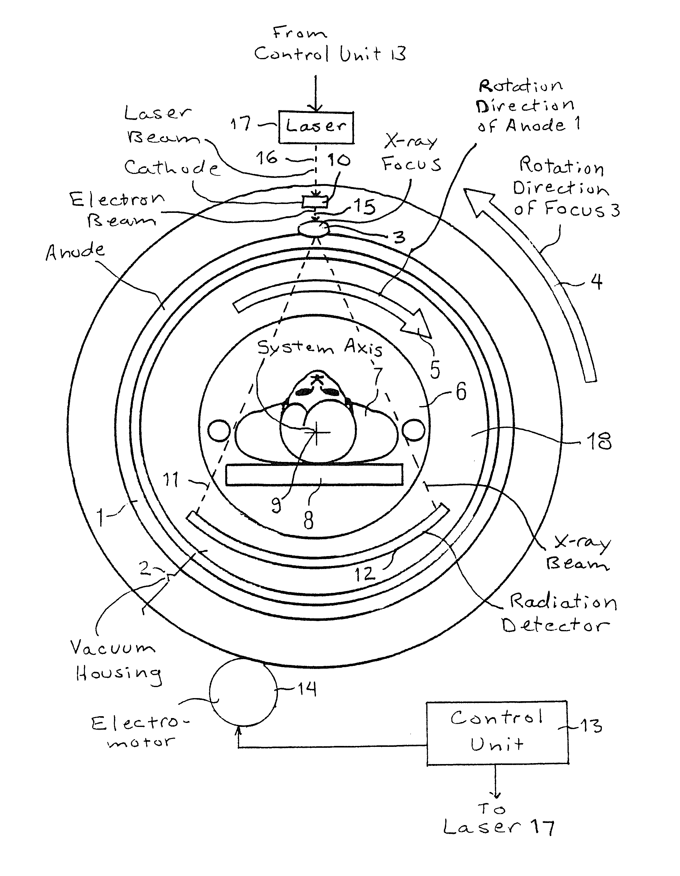
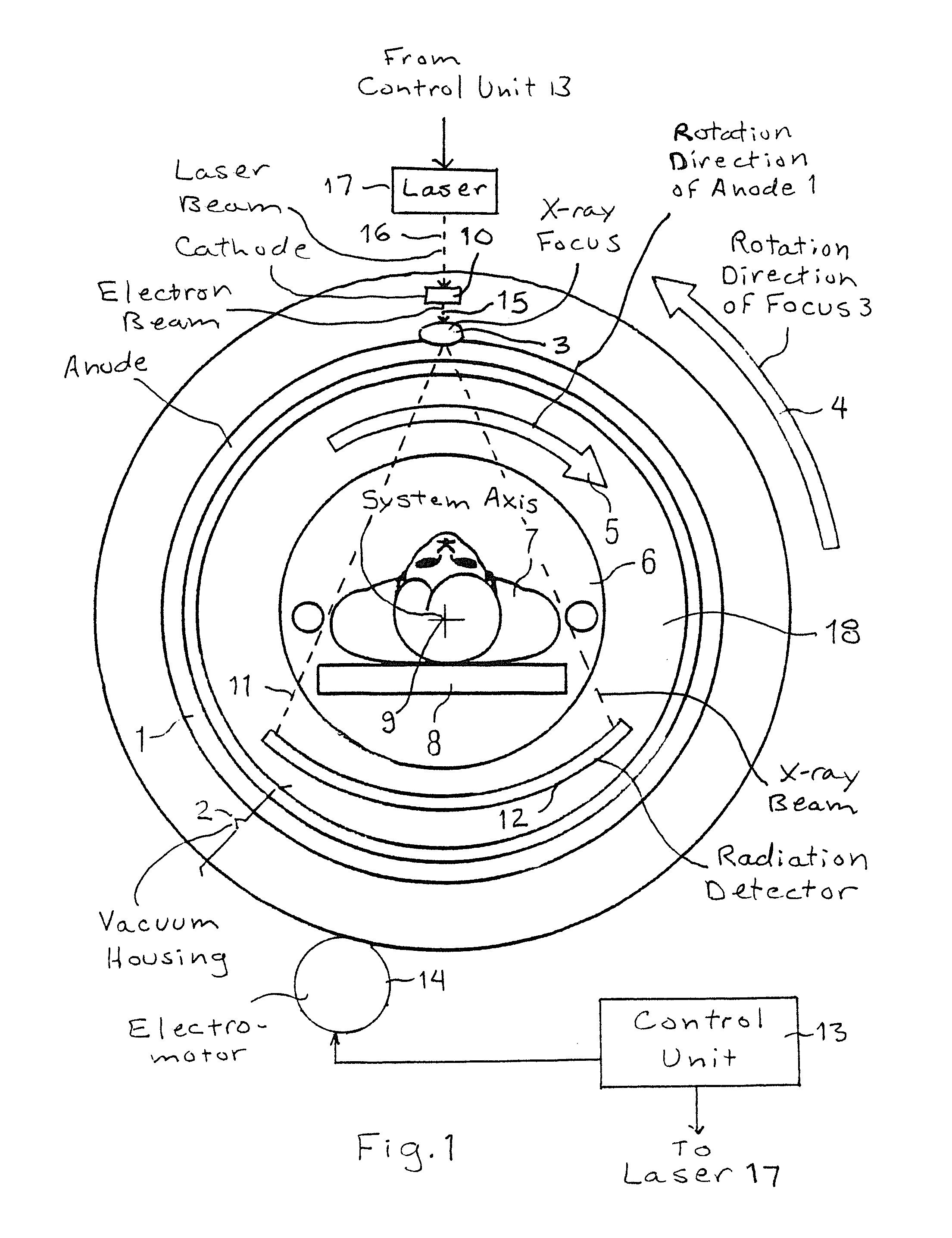
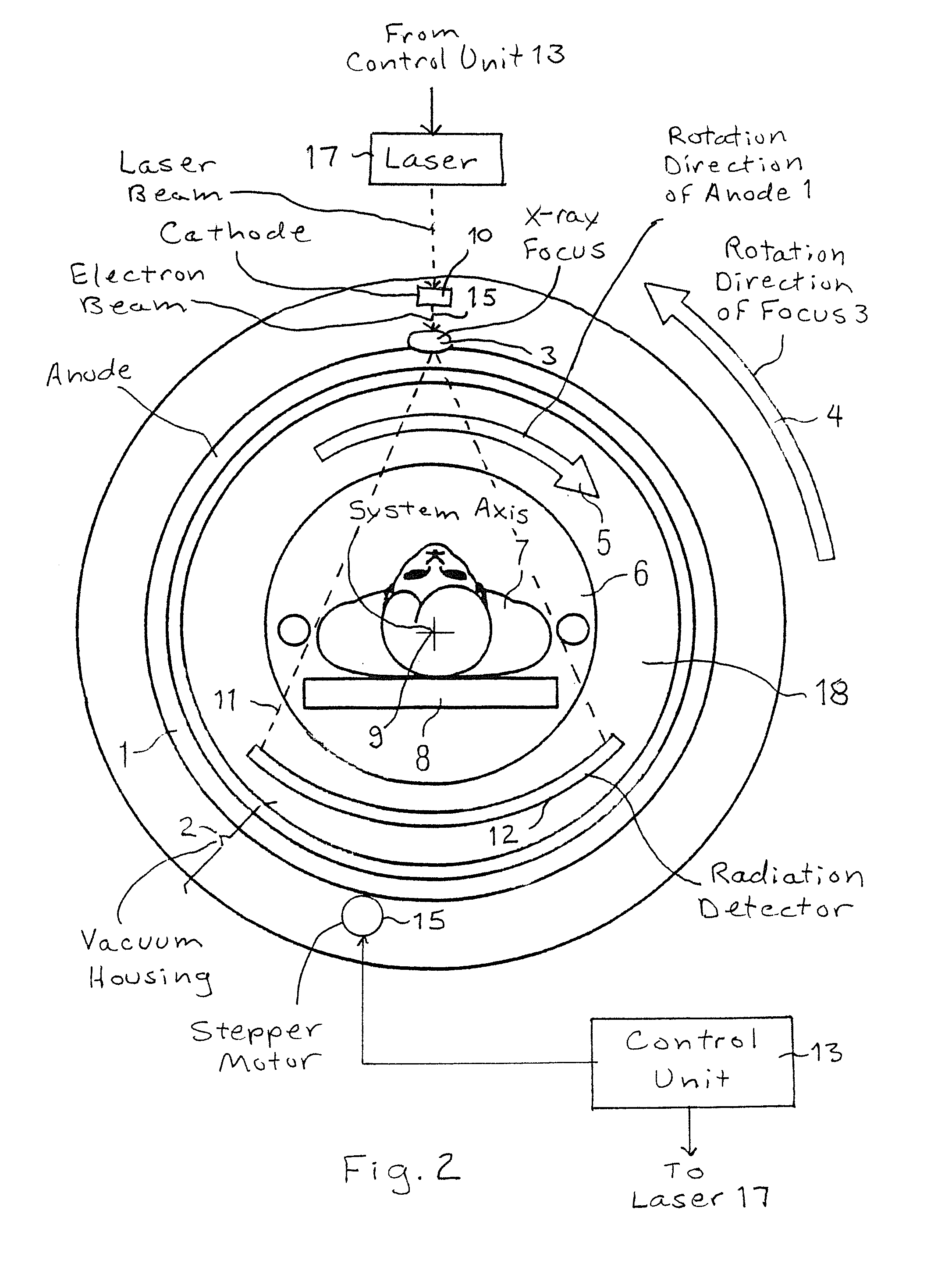
[0029]FIG. 1 shows a schematic representation of an x-ray computed tomography apparatus according to the invention in cross section, perpendicular to the system axis 9 (z-axis). The system axis 9 corresponds to the axis of symmetry of the annular anode 1 that runs perpendicular to the plane of the drawing. The examination volume 6 of the x-ray computed tomography apparatus is entirely enclosed by an annular, stationary vacuum housing 2 and an annular anode 1 borne therein such that it can rotate around the system axis 9. The cross section of a patient 7 on a patient positioning table 8 is schematically shown in the examination volume 6. In the preferred embodiment shown in FIG. 1, the anode 1 is fixed inside the vacuum housing 2, and the vacuum housing 2, with the anode 1 therein, is rotated around the system axis 9 by an actuator such as an electromotor 14. In the embodiment of FIG. 2, an actuator is shown to rotate the anode 1 around the system axis without rotation of the vacuum ...


PUM


Abstract

An x-ray computed tomography apparatus has one anode ring in a vacuum housing surrounding an examination volume, wherein a focus of an x-ray source revolves on the anode ring to expose the examination volume with an x-ray beam from different directions, and a detector system arranged on a rotating frame that can rotate around a system axis. The detector system serves to detect the x-ray radiation exiting from the examination volume, wherein the detector system and the focus can rotate around the system axis synchronously and in the same rotation direction with a rotation angle offset by 180°. The apparatus also includes a computer to process the measurement values acquired by the detector system. The anode ring can be driven such that it rotates around the system axis, and the rotation direction of the anode ring and the rotation direction of the focus around the system axis are opposite while a rotation of the focus around the system axis ensues.

Description

BACKGROUND OF THE INVENTION[0001]1. Field of the Invention[0002]The present invention concerns an x-ray computed tomography apparatus of the type having at least one anode ring in a vacuum housing surrounding an examination volume, wherein a focus of an x-ray source revolves on the anode ring to irradiate the examination volume with an x-ray beam from different directions, a detector system arranged on a rotating frame that can rotate on a system axis to receive the x-ray radiation escaping from the examination volume, wherein the detector system and the focus can be rotated synchronously around the system axis with a rotation angle offset by 180°, and a computer to process the measurement values acquired by the detector system.[0003]2. Description of the Prior Art[0004]X-ray computed tomography systems are used in medical imaging (for example) in order to acquire images of the inside of the body of a patient. An x-ray computed tomography apparatus includes, among other things, a de...

Claims


Application Information

Patent Timeline
Patent Type & Authority Patents(United States)
IPC IPC(8): H01J35/02H01J35/08H05G1/52H05G1/66H01J35/10
CPCA61B6/035A61B6/4028H01J35/08H01J2235/086H01J35/26
Inventor POPESCU, STEFANWITTMANN, GEORG
Owner SIEMENS AG
Why Eureka
Try Eureka