Laser machining apparatus using laser beam introduced into jet liquid column

a laser beam and machine machining technology, which is applied in the direction of welding apparatus, metal-working apparatus, manufacturing tools, etc., can solve the problems of affecting the smooth operation of the machine, so as to improve the propagation efficiency of the laser beam, improve the quality of machining, and reduce the flow speed in the liquid reservoir chamber

Active Publication Date: 2012-03-13
SUGINO MACHINE
View PDF6 Cites 34 Cited by
  • Summary
  • Abstract
  • Description
  • Claims
  • Application Information

AI Technical Summary

Benefits of technology

[0010]In view of the above-described state of the art, an object of the present invention is to provide a laser machining apparatus which can stably generate a water jet for introducing a laser beam.
[0011]Another object of the present invention is to provide a laser machining apparatus using a laser beam introduced into a jet liquid column, which apparatus can improve propagation efficiency of the laser beam and can ensure stable machining quality.

Problems solved by technology

In addition, because thermal lens action is induced by heating generated when the laser beam is absorbed by the water, a difficulty is caused in efficiently introducing the laser beam to the water jet (jet liquid column).
Further, if the laser beam is refracted by the induced thermal lens action, the refracted laser beam may strike against an inlet opening portion of a nozzle, thus damaging the nozzle.
However, when the flow speed of the water in the liquid supply space for introducing the water to the nozzle is increased to reduce the temperature rise of the water, another problem arises in that the shape of the water jet becomes apt to fluctuate and the surface of the water jet is disturbed.
More specifically, if the surface of the water jet is disturbed, the laser beam introduced with the water jet is also affected, thus resulting in deterioration of machining quality of the laser machining apparatus.
In some cases, a very long time is necessary for one cycle of machining performed by the laser machining apparatus depending on the material or dimensions of a machining target.
Further, if the surface of the water jet is disturbed, the laser beam may run out of the water jet without being totally reflected at the surface of the water jet.
Thus, the propagation efficiency of the laser beam is reduced due to the disturbances o the water jet.

Method used


Image

  • Laser machining apparatus using laser beam introduced into jet liquid column
  • Laser machining apparatus using laser beam introduced into jet liquid column
  • Laser machining apparatus using laser beam introduced into jet liquid column

Examples


Embodiment Construction

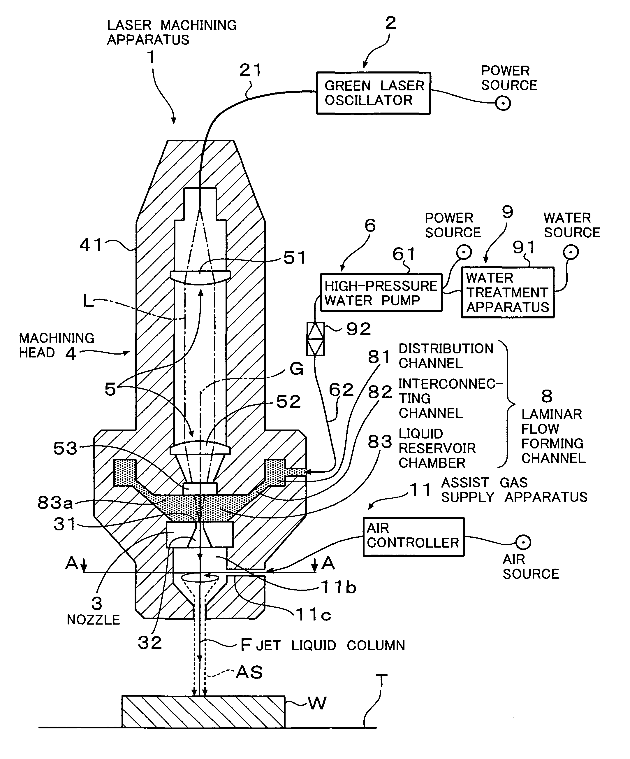
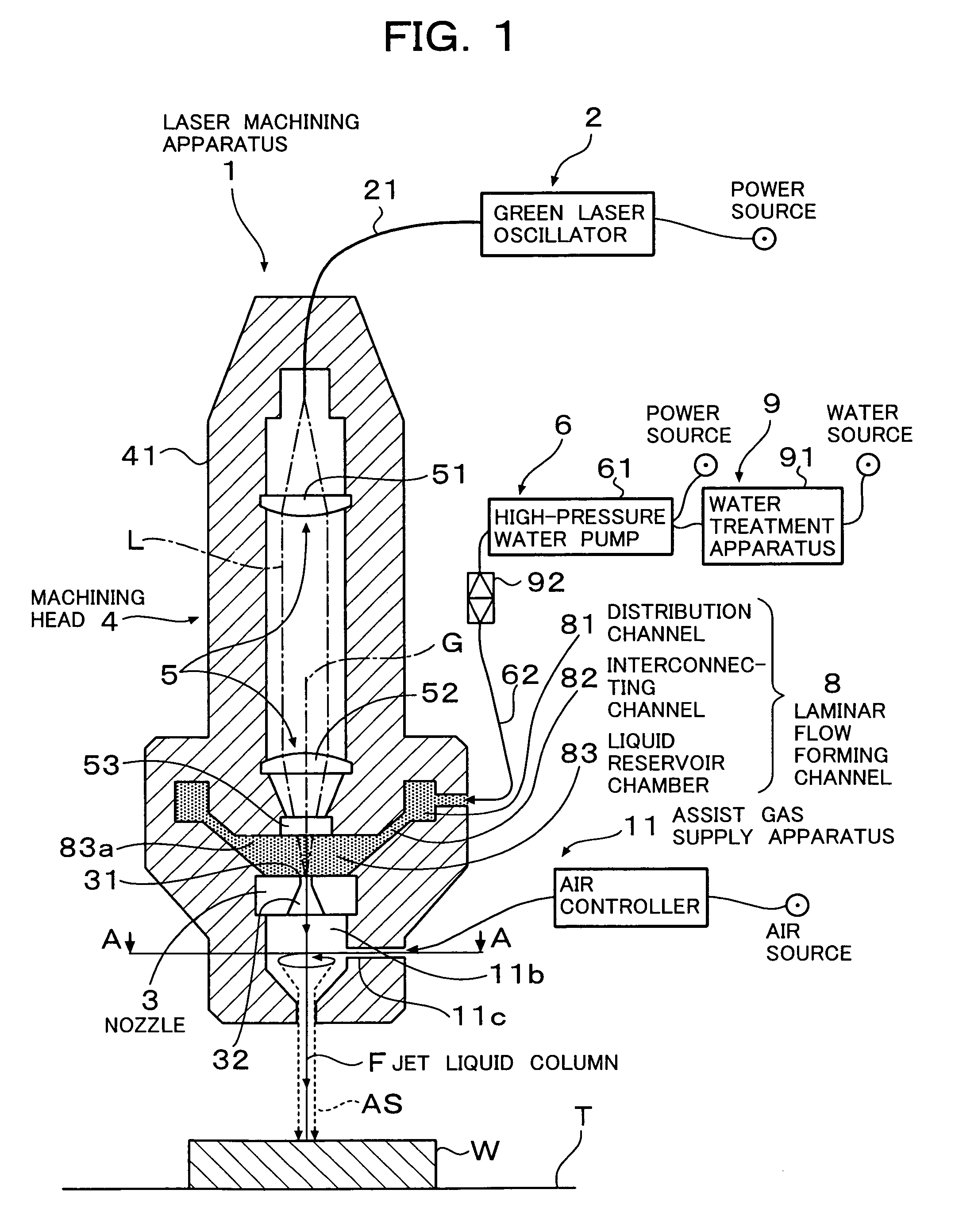
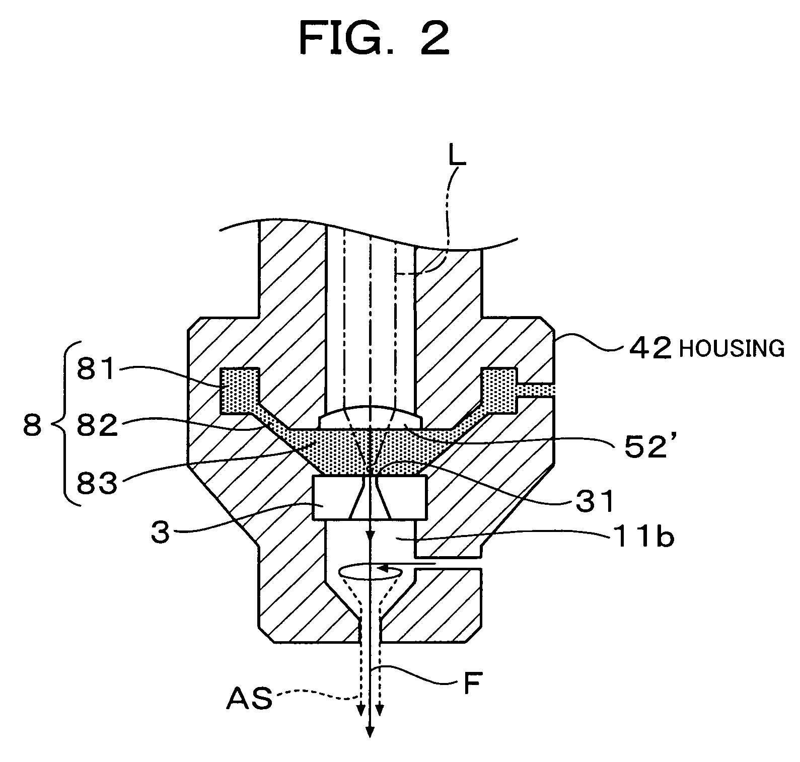
[0068]A laser machining apparatus according to an embodiment of the present invention will be described in detail with reference to the drawings.

[0069]Of the drawings referred to herein, FIG. 1 is a side sectional view showing the overall construction of the laser machining apparatus according to the embodiment of the present invention. FIG. 2 is a partial enlarged view for explaining another example of an optical device used in the embodiment of the present invention, the view showing the case where a laser beam guide window is not provided. FIG. 3 is a perspective view showing the shape of a laminar flow forming channel according to the embodiment of the present invention. FIG. 4 is a sectional view taken along the line A-A in FIG. 1, the view showing the construction of a spiral guide channel in an assist gas supply apparatus according to the embodiment of the present invention. FIG. 5 is a side sectional view showing the construction of a conical guide channel according to anoth...


PUM

PropertyMeasurementUnit
depthaaaaaaaaaa
wavelength rangeaaaaaaaaaa
absorption coefficientaaaaaaaaaa

Abstract

A laser machining apparatus comprises a nozzle for ejecting a jet liquid to a workpiece and a liquid supply unit for supplying the jet liquid to the nozzle, while a laser beam is introduced into a jet liquid column ejected from the nozzle. The laser machining apparatus further comprises a laminar flow forming channel for supplying the jet liquid to the nozzle in a laminar state. The laminar flow forming channel includes a distribution channel formed by a cavity for annually distributing the jet liquid, which is supplied from the liquid supply unit, around an axis of the nozzle, an interconnecting channel disposed to be communicated with the distribution channel at the downstream side thereof in an axial direction of the nozzle and formed by an annular cavity around the axis of the nozzle to provide a narrower flow passage than the distribution channel, and a liquid reservoir chamber adjacently disposed upstream of the nozzle in the axial direction thereof and storing the jet liquid to be supplied to the nozzle. The liquid reservoir chamber has an outer peripheral edge being communicated with the interconnecting channel over an entire circumference of the annular shape thereof.

Description

BACKGROUND OF THE INVENTION[0001]1. Field of the Invention[0002]The present invention relates to a laser machining (processing) apparatus using a laser beam introduced into a jet liquid column. More particularly, the present invention relates to a laser machining apparatus using a laser beam introduced into a jet liquid column, which apparatus can improve propagation efficiency of the laser beam and can ensure stable machining quality.[0003]2. Description of the Related Art[0004]Hitherto, there is known an apparatus for irradiating a laser beam into a jet liquid column of an electrolyte for plating or etching, and performing the plating or the etching on a substrate by utilizing a technique of introducing the laser beam through the jet liquid column. There is also known a therapy apparatus for incising a to-be-treated part with a water jet and a laser beam by irradiating the laser beam into the water jet and propagating the laser beam in the water jet with total reflection.[0005]Suc...

Claims


Application Information

Patent Timeline
Patent Type & Authority Patents(United States)
IPC IPC(8): B23K26/14
CPCB23K26/1417B23K26/146
Inventor MURATSUBAKI, RYOJINAGATA, YUKIAKISUGIMORI, TADASHI
Owner SUGINO MACHINE
Why Eureka
Try Eureka