Apparatus for high density low cost automatic test applications

Active Publication Date: 2012-03-20
SMITH STEPHEN WILLIAM
View PDF14 Cites 49 Cited by
  • Summary
  • Abstract
  • Description
  • Claims
  • Application Information

AI Technical Summary

Benefits of technology

[0006]It is an object of this invention to provide an apparatus to test radio frequency (RF) and/or mixed signal semiconductor devices and or modules. specifically this invention incorporates a number of ingenious concepts which may be used as a part of the tester described herein, but may also be used in other test applications. Because the test apparatus described has a modular construction it may comprise all or any combination of the inventions described herein. One of the inventions described that may form a part of this tester is the distributed stimulus for RF automatic test applications which enables greater test flexibility and provides an economical way to preform parallel device testing thus reducing cost of test by permitting one signal source to be used as a reference for a multiplicity of device test ports.
[0007]The unified testhead for automatic test applications enables the entire tester to be built in one assembly if so desired reducing the floor space required by the tester. This is a significant improvement on existing testers which are either very large and bulky and so take up a lot of floorspace, or are very small with a very limited test capability.
[0008]The reverse card backplane for automatic test applications is a method of leveraging existing backplane technology while still providing both front and back access to test boards/modules enabling better signal integrity and shorter electrical lengths when connecting to the device under test (DUT). Prior art approaches require lengthy cables thus degrading performance.
[0009]The direct coaxial interface for automatic test applications provides a further

Problems solved by technology

This is a significant improvement on existing testers which are either very large and bulky and so take up a lot of floorspace

Method used


Image

  • Apparatus for high density low cost automatic test applications
  • Apparatus for high density low cost automatic test applications
  • Apparatus for high density low cost automatic test applications

Examples


Embodiment Construction

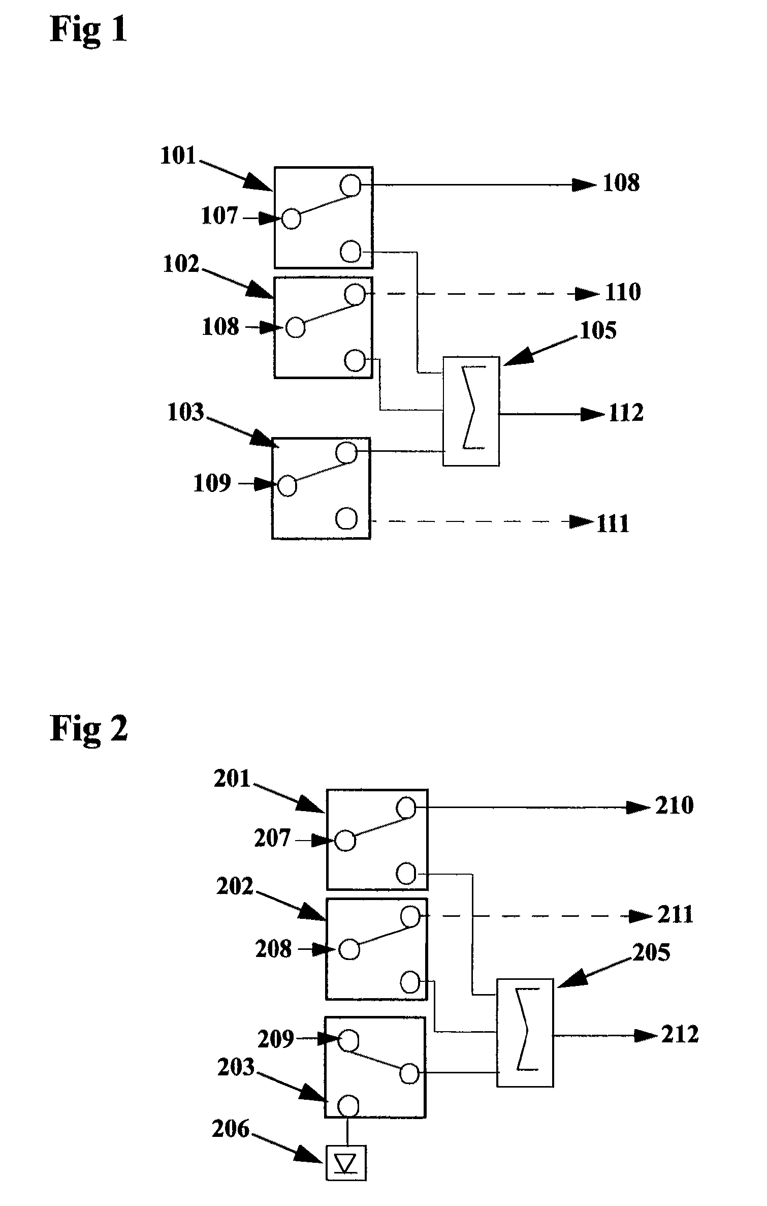
[0039]The distributed stimulus which provides much more test flexibility than prior art permitting signal generators to be combined to produce multiple tones, routed separately to the device Under test (DUT), or combined with an internal calibrated noise source thereby giving multiple signal ports rather than being limited by the prior art approach of having separate combined or non-combined DUT ports with limited test capability.

[0040]FIG. 1 is a block diagram showing an example of a basic distributed stimulus. In this example three input signals 107, 108 and 109 are shown. Input signal 107 is routed to RF switch 101 where it may be switched to DUT port 108 or via combiner 105 to DUT port 112. Likewise Input signal 108 is routed to RF switch 101 where it may be switched to DUT port 110 or combiner 105 to DUT port 112. If both switches are set to combiner 105 then the two incoming sources are combined thereby producing a two-tone signal at DUT port 112 which can be used for wireless...


PUM


Abstract

An apparatus for testing radio frequency (RF) and/or mixed signal semiconductor devices and or modules is described. specifically described is how the distributed stimulus for RF automatic test applications, unified testhead for automatic test applications, reverse card backplane for automatic test applications, direct coaxial interface for automatic test applications, cable-free interface for automatic test applications, micromachine switch matrix for automatic test applications, device specific module high speed date for RF automatic test applications may be used within tester apparatus described herein or in other test applications. Additionally a high speed date communications test apparatus which may be used in a variety of device testers is described herein.

Description

CROSS-REFERENCE TO RELATED INVENTIONS[0001]I claim the benefit of the following provisional patents:[0002]Appl No. 60 / 666,601, filed Mar. 31, 2005:—distributed stimulus for RF automatic test applications, unified testhead for automatic test applications, reverse card backplane for automatic test applications, cable-free RF signal path for automatic test applications, micromachine RF matrix for RF automatic test applications, device specific module for RF automatic test applications.FIELD OF THE INVENTION[0003]The field of the invention relates to automatic test equipment, and more specifically to an apparatus and to novel techniques used therein for the purpose of testing semiconductor devices and / or modules.BACKGROUND[0004]Semiconductor devices or modules are often tested using automatic test equipment (ATE). Generally, the tester includes a computer system that coordinates and runs the tests, and a testing apparatus. Typically testers are costly, bulky machines consuming vast amou...

Claims


Application Information

Patent Timeline
IPC IPC(8): G01R31/00
CPCG01R31/2808G01R31/2822
Inventor SMITH, STEPHEN WILLIAM
Owner SMITH STEPHEN WILLIAM
Why Eureka
Try Eureka