Process and system for providing electrical energy to a shielded medical imaging suite

a technology of electrical energy supply and shielded medical imaging, which is applied in the direction of discharge tube/lamp details, fixed transformers, instruments, etc., can solve the problems of adversely affecting the quality of images produced by the medical imaging system, the inability to use standard electrical supply systems such as alternating current, and the inability to transmit electricity into such rooms. to achieve the effect of reducing the interfering magnetic field in the room

Active Publication Date: 2012-03-20
ACIST MEDICAL SYST
View PDF30 Cites 2 Cited by
  • Summary
  • Abstract
  • Description
  • Claims
  • Application Information

AI Technical Summary

Benefits of technology

[0007]The needs outlined above are met by the present invention which, in various embodiments, provides a system that overcomes many of the technical problems discussed above, as well other technical problems, with regard to the supply of electrical energy to a device (such as, for example, mobile injection units, extravasation detection devices, and / or other devices located within a shielded imaging facility (such as an EM-shielded MRI suite)). Specifically, in one embodiment, a process is provided for providing electrical energy to a device located in an imaging room wherein the imaging room includes shielding against EM fields located outside the room. In one embodiment, the process comprises emitting electromagnetic radiation in the wave length range of the light spectrum from at one least one light emitting device, transforming the electromagnetic radiation into electrical energy using at least one transducer device located in the room, and directing the electrical energy to the device so as to minimize interfering magnetic fields in the room.
[0010]Various embodiments of the present invention also provide a system for providing electrical energy to a device located in an imaging system room wherein the room includes shielding against EM fields located outside the room. In one embodiment, the system comprises a light emitting device for emitting electromagnetic radiation in the wave length range of the light spectrum and a transducer device located in the room for transforming the electromagnetic radiation into electrical energy. The transducer device is also configured to be capable of directing the electrical energy to the device so as to minimize interfering magnetic fields in the room.
[0014]Thus, the systems and processes for providing electrical energy to a device located in an imaging system room (such as an MRI system room), as described in the embodiments of the present invention, provide many advantages that may include, but are not limited to: transmitting energy to a device in the form of electromagnetic radiation within the wavelength of the light spectrum so as to avoid the generation of electromagnetic fields that may interfere with the operation of an imaging device (such as an MRI system, for example) co-located with the device; eliminating and / or minimizing the need for EM shielding around electrical energy transmission cables within an imaging room; and generating the electromagnetic radiation in the light spectrum using a light-emitting device located outside a shielded imaging room so as to avoid the generation of interfering EM fields by the light-emitting device.

Problems solved by technology

Where rooms are shielded from potentially interfering electromagnetic (EM) fields, as is sometimes necessary in medical imaging suites (such as MRI imaging suites, for example), the transmission of electricity into such rooms can be problematic.
For example, it is not possible to use standard electrical supply systems, such as an alternating current form, without special screening in the particularly sensitive area of the medical imaging device (such as MRI, for example) due to the generally large interference fields generated by such electrical supply systems.
An electrical supply cable of such length may result in unacceptable interference fields that adversely affect the quality of the images produced by the medical imaging system.
One disadvantage of this approach is that the battery must be changed and / or re-charged regularly thereby interfering with the operability of the medical imaging system.
The use of a rechargeable accumulator, however, also requires regular maintenance.
Such maintenance delays, including the exchange and the associated “running in” of new accumulators, are likewise disadvantageous to the standard long-term operation of the medical imaging system.
Furthermore, in existing systems, the malfunction of either a battery or an accumulator, for example, within the imaging suite may lead to potential sources of interference that may, in turn, adversely affect the operation of the imaging system (such as an MRI system, for example).

Method used


Image

  • Process and system for providing electrical energy to a shielded medical imaging suite
  • Process and system for providing electrical energy to a shielded medical imaging suite
  • Process and system for providing electrical energy to a shielded medical imaging suite

Examples


Embodiment Construction

[0018]The present inventions now will be described more fully hereinafter with reference to the accompanying drawings, in which some, but not all embodiments of the invention are shown. Indeed, these inventions may be embodied in many different forms and should not be construed as limited to the embodiments set forth herein; rather, these embodiments are provided so that this disclosure will satisfy applicable legal requirements. Like numbers refer to like elements throughout.

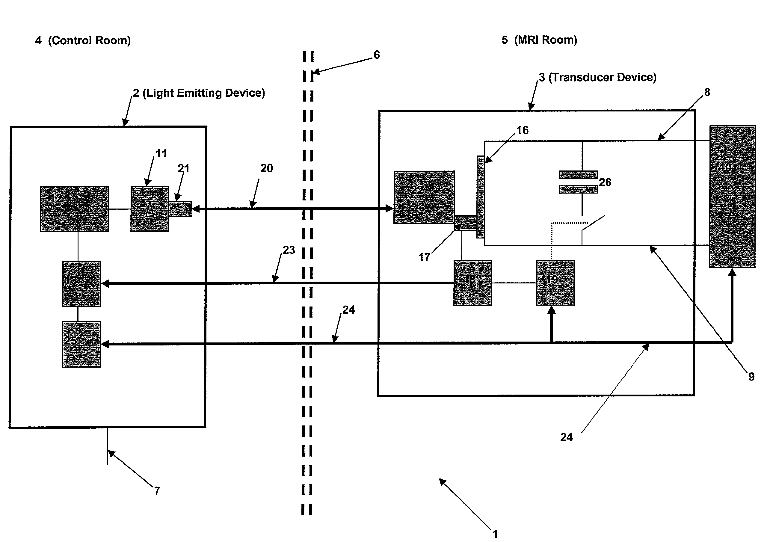
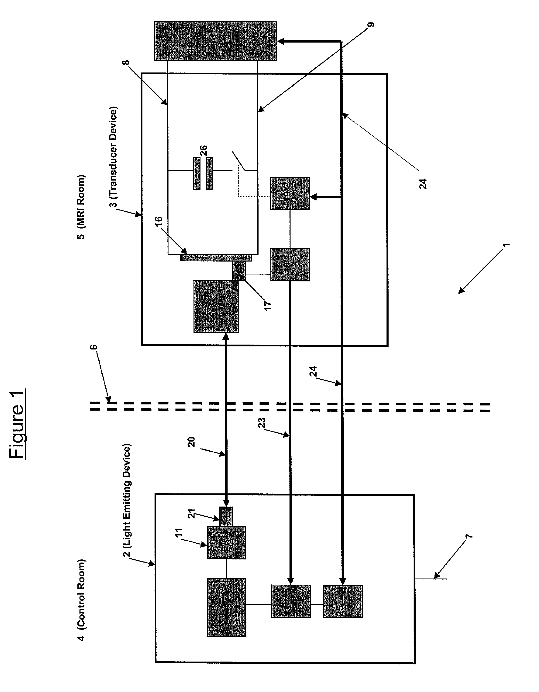
[0019]According to one embodiment, as shown in FIG. 1, the system 1 for the provision of electrical energy comprises a light emitting device 2 for emitting electromagnetic radiation in the wavelength range of the light spectrum and a transducer device 3, located in an imaging room 5 (such as a room within a medical imaging suite housing an MRI or other imaging device), for transforming the electromagnetic radiation into electrical energy and directing the electrical energy to the device 10 so as to minimize int...


PUM


Abstract

A process and system are disclosed for supplying electrical energy to a device located in a room housing an imaging system (such as an MRI system, for example), wherein the room is shielded from external electromagnetic fields. Certain embodiments of the present invention provide systems and processes for emitting electromagnetic radiation in the wavelength range of the light spectrum from at least one light emission device. Embodiments of the present invention further provide a process and system for transforming the electromagnetic radiation into electrical energy using at least one transducer device located in the room, and supplying the electrical energy to the device so as to minimize interfering electromagnetic fields within the room.

Description

FIELD OF THE INVENTION[0001]Embodiments of the present invention provide a process and system for supplying electrical energy to a device in an imaging room.BACKGROUND OF THE INVENTION[0002]Where rooms are shielded from potentially interfering electromagnetic (EM) fields, as is sometimes necessary in medical imaging suites (such as MRI imaging suites, for example), the transmission of electricity into such rooms can be problematic. For example, it is not possible to use standard electrical supply systems, such as an alternating current form, without special screening in the particularly sensitive area of the medical imaging device (such as MRI, for example) due to the generally large interference fields generated by such electrical supply systems. However, within a medical imaging suite, it is necessary that there is a dependable supply of electrical energy for devices located within the medical imaging suite.[0003]One example of a device often utilized in an imaging suite (such as ...

Claims


Application Information

Patent Timeline
Patent Type & Authority Patents(United States)
IPC IPC(8): H04B10/00
CPCG01R33/283G01R33/28
Inventor JAUSTER, RALFCOENEN, PAULFRIEBE, MICHAEL
Owner ACIST MEDICAL SYST
Why Eureka
Try Eureka