Self-contained system for scavenging contaminated air from above the water surface of an indoor swimming pool

a self-contained system and indoor swimming pool technology, applied in ventilation systems, heating types, separation processes, etc., can solve the problems of compound exposure to certain types of cancer, eye, nose and throat irritation, corrosion of pool building components and equipment, etc., and achieve the effect of effective scavenging and minimizing mixing with room air

Active Publication Date: 2015-04-07
BAKER DONALD C
View PDF20 Cites 11 Cited by
  • Summary
  • Abstract
  • Description
  • Claims
  • Application Information

AI Technical Summary

Benefits of technology

[0011]In accordance with one embodiment, a self-contained scavenging system positively displaces and removes contaminated air from the volume just above the waterline of indoor swimming pools, and exhausts the contaminated air outside the natatorium, or strips the contaminants from the exhaust air stream and returns clean air to the natatorium. The system includes a means to supply controlled-velocity laminar flow scavenging air on one side of an indoor swimming pool and a means to extract scavenging air and contamination on the other side of the pool, using substantially less airflow than existing systems. This embodiment uses laminar flow ventilation, also called piston ventilation, in which the air moves with essentially equal velocity (piston-like bulk flow of a mass of air) as measured across the dimension longitudinally and vertically perpendicular to the direction of the flow. Laminar flow ventilation minimizes mixing of contaminated air with environmental air that is controlled by a natatorium HVAC system.
[0015]In still another embodiment, the intake fan pulls clean, conditioned air from the natatorium space and distributes this clean air to the pressure plenum disposed near the waterline on the first side of the pool. Air from the pressure plenum is uniformly presented to the laminar flow diffuser that generates, by virtue of its shape and dimensions, a piston-like laminar flow of air. The centerline of the piston-like laminar flow is parallel to the waterline, and extends vertically from near the waterline to the top of the laminar flow diffuser and longitudinally along the entire length of the first side of the pool. The laminar piston-like flow, which is approximately rectangular in cross-section and which moves in bulk at a uniform rate, is directed perpendicularly from the first side of the pool, across the water surface, and toward the opposing second side of the pool, setting up a uniformly-moving blanket of air that remains attached to the surface of the water. This moving blanket of air, which is only of necessary and sufficient size and velocity to effectively scavenge the gaseous contaminants located just above the water surface, carries with it the gaseous contaminants and presents these contaminants to the laminar flow collection diffuser located near the waterline on the opposing second side of the pool. The moving blanket of air, generated by a multiplicity of air jets from the laminar flow diffuser, is independent of air movements generated by the natatorium HVAC system and is configured such that laminar flow is achieved and mixing with room air is minimized. As the contaminated air nears the opposing second side of the pool and the laminar flow collection diffuser near the waterline on the opposing second side of the pool, the negative pressure set up in the collection plenum by the exhaust fan pulls the contaminated air through the laminar flow collection diffuser into the collection plenum which is connected by suitable ductwork to the exhaust fan and subsequently to a contaminant-stripper or contaminant destruction device, after which the contaminant-free air is returned to the natatorium.

Problems solved by technology

It causes eye, nose and throat irritation, has been linked to asthma-like symptoms, and causes corrosion on pool building components and equipment.
Organic DBPs, such as trihalomethanes, are also present in the air in indoor swimming pools and this class of compounds has been linked to an increased risk for certain types of cancer.
Some devices, systems and methods are directed toward preventing the formation of DBP contaminants in the water by eliminating or minimizing the introduction of nitrogen-containing organic compounds into pool water (nitrogen-containing compounds which react with chlorine or bromine used for disinfecting pool water are responsible for forming these contaminants); these methods have proved to be impractical because swimmers are the primary source of nitrogen-containing compounds.
Other systems rely on medium-pressure ultraviolet (UV) light devices to destroy DBP contaminants in the water in the water treatment room before they volatilize and appear in the air; these systems have been demonstrated to be less than totally effective because the creation and volatilization of DBPs can occur before the water can be recycled back to the UV unit.
The most common method for controlling off-gassed DBPs relies on the air handling system (HVAC) in the natatorium (swimming pool enclosure) to progressively dilute the concentration of gaseous contaminants through multiple air changes utilizing a large percentage of outside air, until the concentration of contaminants no longer poses a health risk; these methods frequently fail because the energy penalty for heating, cooling and / or dehumidifying large quantities of outside air is too great.
These systems are not capable, on their own, of removing contaminated air from the surface of a pool due to the fact that suction returns cannot independently draw in air and contaminants from a distance of more than a few feet from the face of the return.
These suction systems are even less capable of drawing contaminated air in a direction opposed to the direction of the air circulation caused by the HVAC system; they are, in fact, dependent upon the HVAC system circulation to push contaminated air in the direction of the gutter or pool-side exhaust.
These systems are not designed to selectively place airflow in the area where it is needed (the area just above the water surface where the concentration of DBPs is highest), are not designed to localize and control the air supply such as to minimize the amount of air employed to remove contaminated air from the surface of a pool, and are not designed to minimize turbulent mixing of the supplied clean air with the contaminated air.
Turbulent mixing of the contaminated air with clean air results in contaminated air being recirculated throughout the natatorium.
Requiring the HVAC system to perform all these normal functions, plus the function of sweeping the pool surface in a carefully controlled manner with minimal expenditure of energy and in the preferred direction to drive contaminated air to the gutter or pool-side return and exhaust, presents a difficult and complex design challenge.
It requires the use of large quantities of air and results in an unnecessarily complex and expensive system with high operational costs.

Method used


Image

  • Self-contained system for scavenging contaminated air from above the water surface of an indoor swimming pool
  • Self-contained system for scavenging contaminated air from above the water surface of an indoor swimming pool
  • Self-contained system for scavenging contaminated air from above the water surface of an indoor swimming pool

Examples


Embodiment Construction

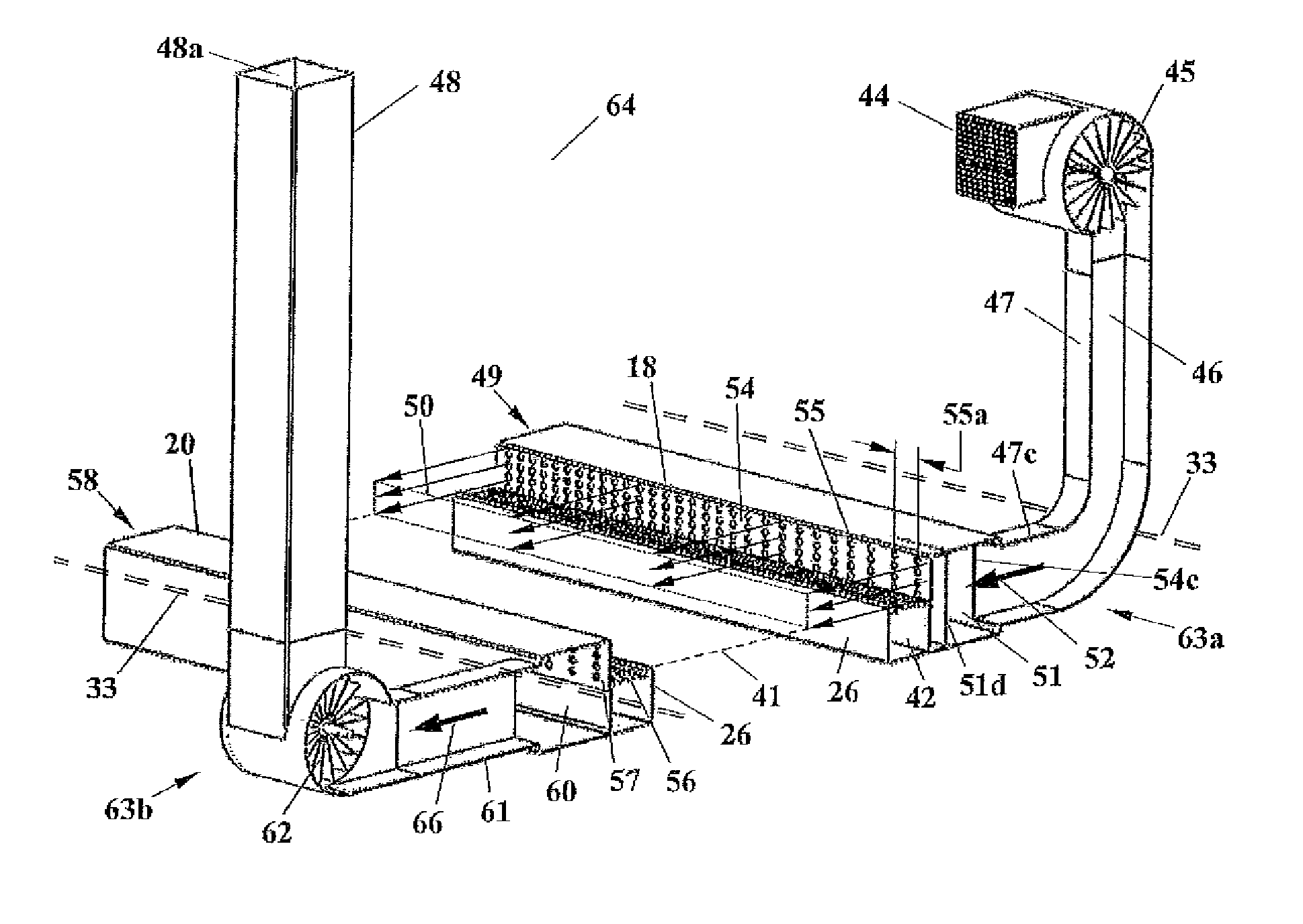
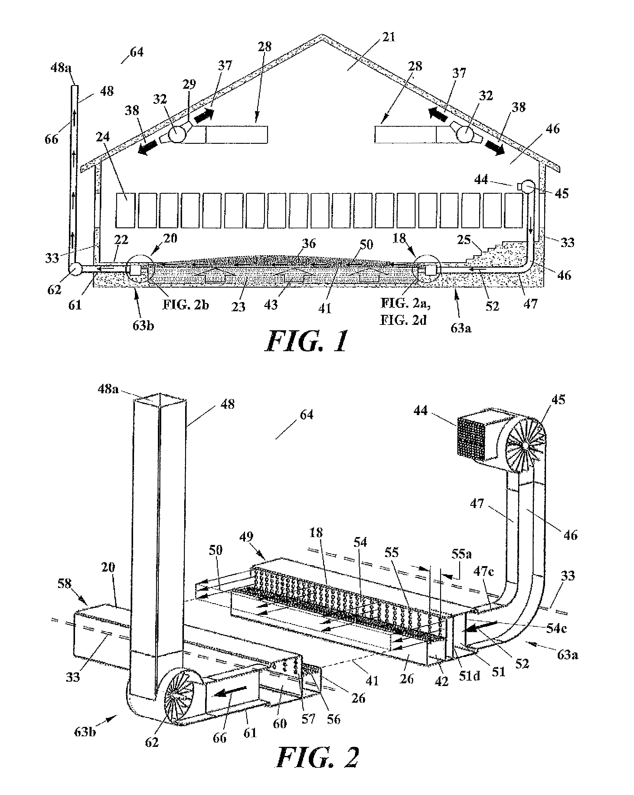
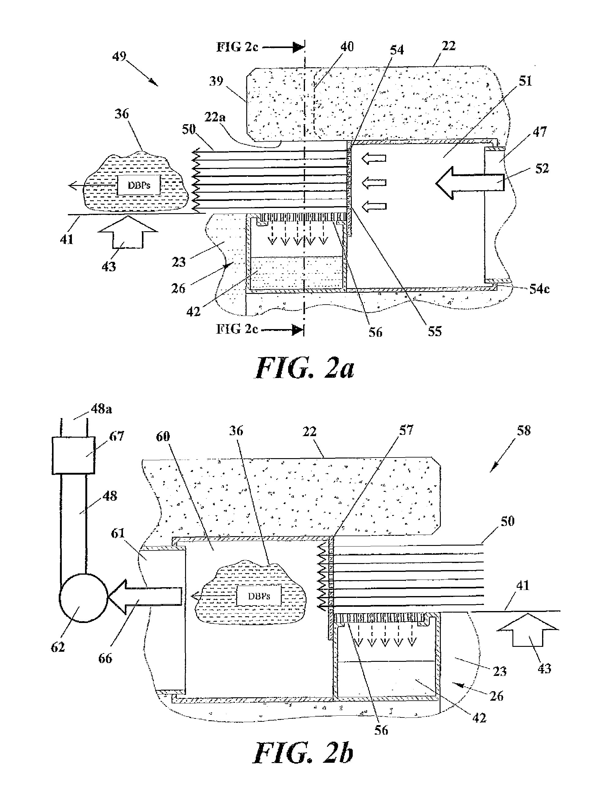
[0010]Apparatus and methods are disclosed for removing disinfectant by-product contaminants that escape into the air above the water surface of an indoor swimming pool. The apparatus and methods provide a self-contained system that operates essentially independently of the HVAC system that services the building surrounding the indoor swimming pool. The apparatus and methods displace and remove contaminated air from the volume of air that sits immediately above the waterline of indoor swimming pools. The apparatus and methods employ a laminar piston-like mass of air that is continuously generated from one side of the pool, sweeps across the water surface of the pool to the opposite side of the pool and is sucked away from the opposite side of the pool. The apparatus and methods are equally applicable to a modified perimeter gutter system and to a gutter-less pool system and can employ air supply fans, air exhaust fans, specialized laminar air flow diffusers, associated plenums and du...


PUM

PropertyMeasurementUnit
Reynolds Numberaaaaaaaaaa
areaaaaaaaaaaa

Abstract

Apparatus and methods are disclosed for removing disinfectant by-product contaminants from the air above the water surface of an indoor swimming pool. The apparatus and methods employ a laminar piston-like mass of air that is continuously generated from one side of the pool, sweeps across the water surface of the pool to the opposite of the pool and is sucked away from the opposite side of the pool. The apparatus and methods are applicable to a modified perimeter gutter system and can employ air supply fans, air exhaust fans, specialized laminar air flow diffusers, associated plenums and ducting and contaminant strippers.

Description

CROSS-REFERENCE TO RELATED APPLICATIONS[0001]The present application hereby incorporates herein in its entirety by this reference for all purposes, the entire disclosure of U.S. Provisional Patent Application Ser. No. 61 / 802,702 filed Mar. 17, 2013.STATEMENT REGARDING FEDERALLY SPONSORED RESEARCH OR DEVELOPMENT[0002]Not applicable.FIELD OF THE INVENTION[0003]The subject matter disclosed herein generally involves apparatus and methods of removing contaminants from the air above the water surface of an indoor swimming pool.BACKGROUND OF THE INVENTION[0004]During the operation of an indoor swimming pool, halogen-based disinfectants such as chlorine or bromine are utilized to react with and remove harmful bacteria and organic materials from the swimming pool water. Compounds referred to as disinfectant by-products (DBPs) are formed as a consequence of the disinfection reactions. Trichloramine, one of the most important of these compounds, off-gasses from swimming pool water and accumula...

Claims


Application Information

Patent Timeline
Patent Type & Authority Patents(United States)
IPC IPC(8): F24F7/00E04H4/06E04H4/14F24F7/08F24F13/28
CPCE04H4/14E04H4/06F24F7/08F24F13/28
Inventor BAXTER, RANDY CARROLL
Owner BAKER DONALD C
Why Eureka
Try Eureka