
Method for operating an internal combustion engine

a technology of internal combustion engine and combustion chamber, which is applied in the direction of electrical control, process and machine control, instruments, etc., can solve the problems of delayed combustion, inability to operate the internal combustion engine with such a “non-conventional” combustion process, and inability to achieve the operation of the internal combustion engine, etc., and achieve the effect of great expenditur

Inactive Publication Date: 2012-03-27
ROBERT BOSCH GMBH
View PDF23 Cites 8 Cited by
  • Summary
  • Abstract
  • Description
  • Claims
  • Application Information

AI Technical Summary

Benefits of technology

The present invention relates to a method for improving the operation of an internal combustion engine by optimizing the rotation variable, which is a measure of the rotational movement of the crankshaft. The method is particularly useful in diesel engines and can be used in a variety of operating states. By adapting the quantity of fuel injected and the amount of fresh air, as well as the amount of exhaust-gas recirculation, the method can reduce differences and fluctuations in the rotation variable, improving the engine's performance and reducing emissions and fuel consumption. The method can be carried out without the need for costly pressure measurements or complex evaluations of structure-borne noise signals. The rotation variable can be used to determine the combustion position and torque output of the engine, providing valuable information for open-loop and closed-loop control.

Problems solved by technology

In reality, however, this is not the case.
It may be that operation of the internal combustion engine with such a “non-conventional” combustion process is not possible in the entire speed range and load range, but is possible in a relatively large range relevant with respect to emissions.
However, high exhaust-gas recirculation rates increase the ignition lag up to values which lead to delayed combustions.
Under unfavorable conditions, misfirings even occur.

Method used


Image

  • Method for operating an internal combustion engine
  • Method for operating an internal combustion engine
  • Method for operating an internal combustion engine

Examples


Embodiment Construction

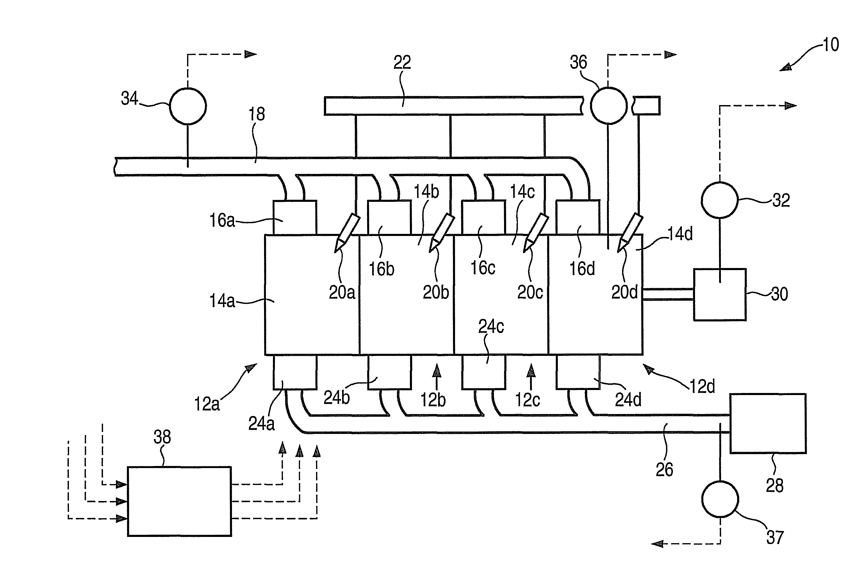
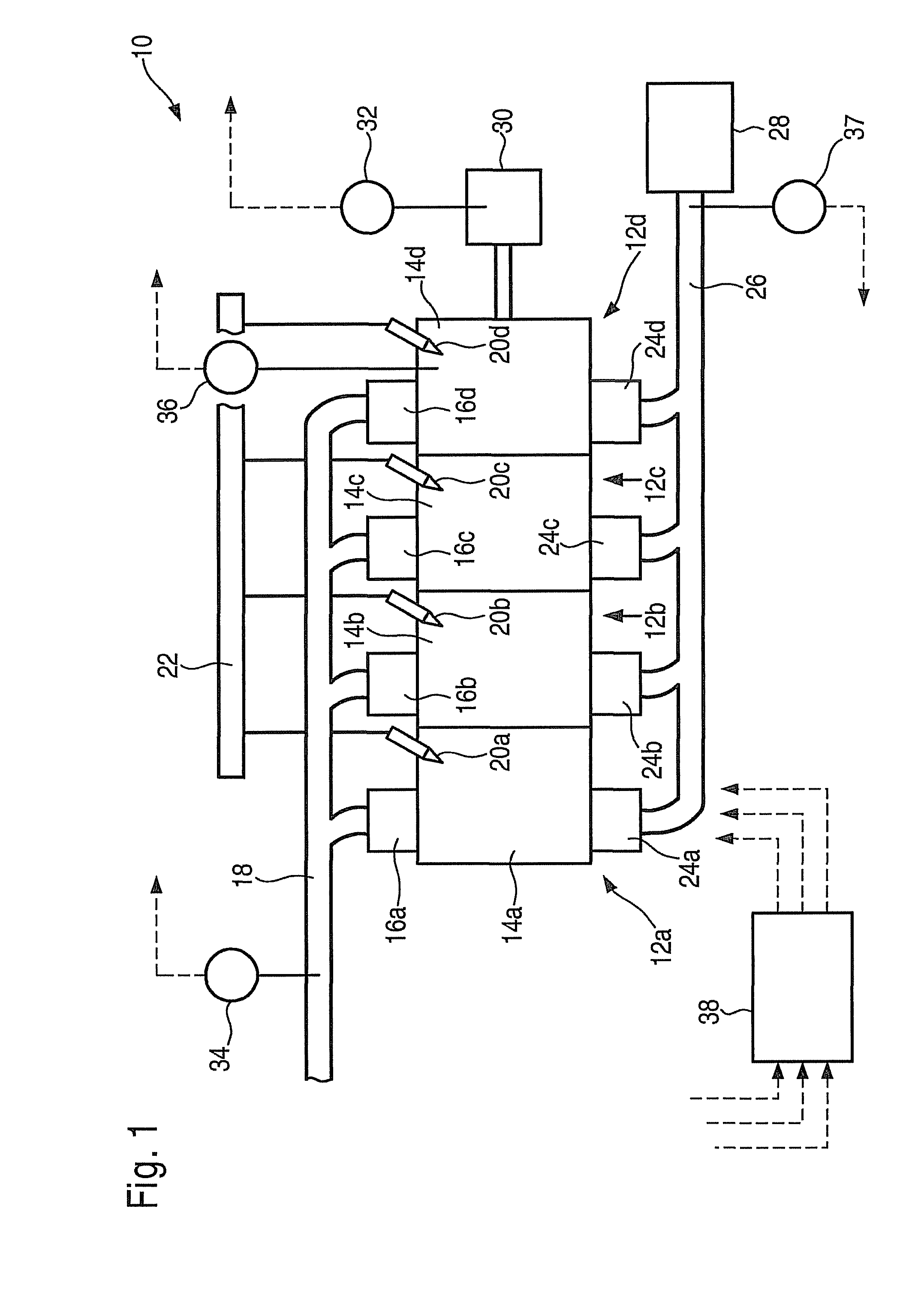
[0021]In FIG. 1, an internal combustion engine is designated overall by reference numeral 10. In the case at hand, it includes a total of four cylinders 12a, 12b, 12c and 12d. They in turn are provided with combustion chambers 14a through d, into which fresh air arrives via an intake valve 16a through d and an intake manifold 18. Fuel is injected into combustion chambers 14a through d through injectors 20a through d, which are connected to a shared high-pressure fuel accumulator 22, also known as a “rail.”

[0022]Combustion exhaust gases are conducted out of combustion chambers 14a through d with the aid of exhaust valves 24a through d into an exhaust pipe 26 to an exhaust-gas treatment device 28. During operation of internal combustion engine 10, a crankshaft 30 is set into rotation whose speed, i.e., rotational speed and rotational acceleration (=“rotation variables”), is recorded by a crankshaft sensor 32 having extremely high time resolution. A fresh-air mass flowing via intake ma...


PUM


Abstract

In an internal combustion engine, at least one rotation variable characterizing the rotational movement of a crankshaft is ascertained cylinder-specifically. It is provided that, in an operating state in which differences and / or fluctuations of the rotation variable are basically a function of a combustion position, the instant of a fuel injection is adapted cylinder-specifically in order to reduce the differences and or fluctuations.

Description

FIELD OF THE INVENTION[0001]The present invention relates to a method for operating an internal combustion engine.BACKGROUND INFORMATION[0002]German Patent Application No. DE 195 27 218 A1 describes a quantity-compensation control. In that case, disparities in the fuel quantity injected into the individual cylinders are inferred from irregularities of the crankshaft rotation, thus, from the extent of the cylinder-specific rotational accelerations within one working cycle. This is based on the following consideration: The heat released during a combustion in the combustion chamber is converted into mechanical work upon expansion of the gas in the cylinder, and accelerates the crankshaft. Ideally, the torque shares of all cylinders of an engine are identical. In reality, however, this is not the case. Differences in the torque shares give rise to differences in the acceleration of the crankshaft, which can be recorded by a speed sensor. In many operating situations, different torque s...

Claims


Application Information

Patent Timeline
Patent Type & Authority Patents(United States)
IPC IPC(8): F02D41/14
CPCF02D41/0085F02D41/1498F02D41/0002F02D41/0057F02D41/3035F02D41/401F02D2200/1012F02D41/04F02D35/00F02D43/00
Inventor WAGNER, HORSTKESSLER, MICHAELWUNDERLIN, SIMONDAMITZ, JENSBOSSMEYER, THOMAS
Owner ROBERT BOSCH GMBH
Learn More