Method and device for decorating an uneven surface of a dimensionally stable object

a dimensionally stable object and uneven surface technology, applied in the direction of typewriters, power drive mechanisms, printing, etc., can solve the problems of increased lacquer consumption, difficult lacquer or printing on that region, and inability to precisely distribute the lacquer with such a method, and achieve the effect of stable in respect of shap

Inactive Publication Date: 2012-03-27
BALL PACKAGING EUROPE
View PDF22 Cites 11 Cited by
  • Summary
  • Abstract
  • Description
  • Claims
  • Application Information

AI Technical Summary

Benefits of technology

[0011]The invention concerns decorating objects which are stable in respect of shape, that is to say objects which retain their configuration in spite of the effect of gravity. They can include for example glass, porcelain, ceramic, plastic material, metals or other materials.
[0012]It may be desirable if prior to the decoration operation a desired paint layer thickness is established in dependence on the location on the uneven surface to be decorated of the object and the control program is created in dependence on the predetermined height profile of the surface to be decorated and the desired paint layer thickness, wherein the digital printing head is controlled with the created control program in response to the topography of the uneven surface to be decorated to produce the predetermined desired paint layer thickness. In that case depending on the respective use involved the desired paint layer thickness can be the same over the entire surface to be decorated or can also vary in any desired fashion. For example it is possible to specify for the desired paint layer thickness a functional relationship in dependence on the positional coordinates of the surface to be decorated. In that case for actuating the printing head the control program takes account of the predetermined height profile of the surface to be decorated in order to produce the predetermined desired paint layer thickness at the respective location on the surface to be decorated of the object. In the case of lacquering the bottom of a beverage can the printing head can precisely be actuated in such a way that the desired lacquer layer thickness in the region of the surface on which the can stands is greater than in other regions of the can bottom.

Problems solved by technology

The described three-dimensional profile of the can bottom makes it difficult to lacquer or print on that region of the can.
Exact lacquer distribution is not possible with such a method.
The described method of lacquering the bottom of a beverage can suffers however on the one hand from the disadvantage that the spray lacquering operation results in the formation of a lacquer mist which is also referred to as overspray and which causes an increased consumption of lacquer and requires suction removal measures to prevent that lacquer mist from being deposited at other locations on the can or to clean the air affected thereby.
At the same time the described method also requires overlacquering of the body portion of the can as it is not possible to lacquer defined portions with a spray lacquering process, but only roughly differentiated portions.
Spray lacquering the bottom of the can in addition also suffers from the disadvantage that solvent-bearing lacquers are generally used in that case, and they entail in particular pertinent environmentally related problems.
Admittedly no overspray is produced by such a method, but the three process steps specified make the method comparatively complicated and expensive.
As the roller lacquering operation is carried out in mass transport of the cans, minor differences in the can height can occur and in addition the application roller cannot be held in every case parallel to the conveyor belt, the lacquer thicknesses which can be produced in the region of the bottom support surface can be kept within predetermined limits only with difficulty.

Method used


Image

  • Method and device for decorating an uneven surface of a dimensionally stable object
  • Method and device for decorating an uneven surface of a dimensionally stable object
  • Method and device for decorating an uneven surface of a dimensionally stable object

Examples


Embodiment Construction

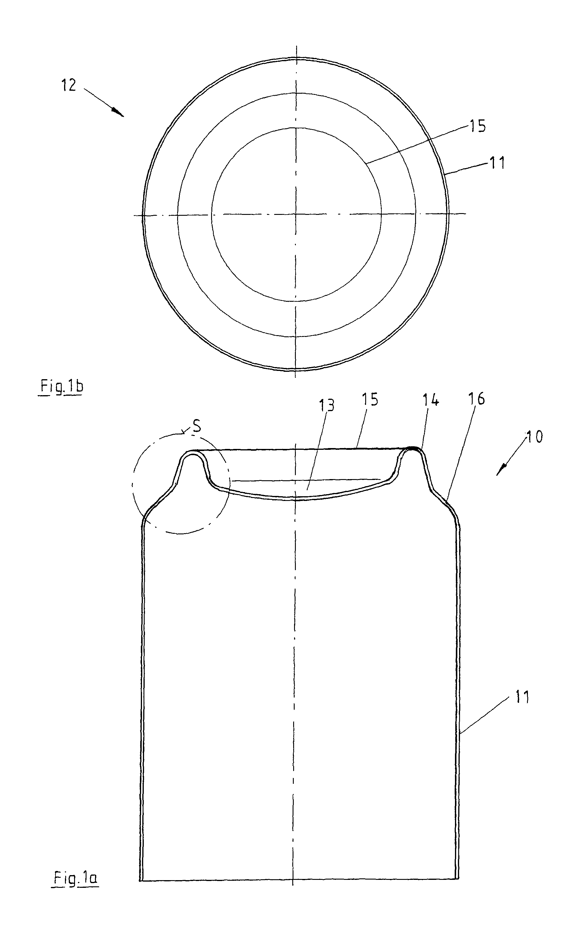
[0037]The invention is described hereinafter with reference to lacquering the bottom of a beverage can. Such a beverage can is generally of a two-part design configuration and comprises in a one-piece structure a can body portion which is produced by way of a drawing-stretching shaping operation and which after filling of the can is closed with a lid. Hereinafter that lid can be disregarded as the invention is described with reference to lacquering of the can bottom.

[0038]FIG. 1a shows a sectional view of the can body portion in an upside-down position. FIG. 1b shows a plan view of the can bottom. The can body portion 10 is composed of a peripheral surface portion 11 and the actual bottom 12, reference 16 denoting a transitional region. Centrally relative to the axis the bottom has a domed portion 13 which radially outwardly goes into a support region 14 in the form of an annular ridge or outwardly curved portion. The extreme points, that is to say the lowest points in the base of t...


PUM


Abstract

A method for decorating an uneven surface of a dimensionally stable object is disclosed. According to the method, the object to be decorated and a digital, contactless printing head are moved in relation to one another during the printing operation and the printing head is controlled by a control unit in order to dispense ink. The method according to the invention comprises the following steps: a control program is created to control the printing head in accordance with the height profile of the uneven surface to be decorated of the object; the position of the surface to be decorated is detected in relation to the printing head; and the digital printing head is controlled using the program that has been created. The invention also relates to a device for carrying out the method.

Description

CROSS-REFERENCE TO RELATED APPLICATIONS[0001]This application is a 371 of PCT / DE2007 / 001299 filed Jul. 20, 2007, which in turn claims priority of de 10 2006 034 060.4 filed Jul. 20, 2006, the priority of both applications is hereby claimed and both applications are hereby incorporated by reference herein.BACKGROUND OF THE INVENTION[0002]The invention concerns a method of and apparatus for decorating an uneven surface on an object which is stable in respect of shape, in particular for decorating a bottom of a beverage can.[0003]In two-part aluminum or tin plate beverage cans available on the market nowadays, the actual Body portion of the can is produced from a single sheet metal portion in a stretching and drawing shaping process. Usually the bottom has a domed portion which goes into an annular ridge providing the surface on which the can body portion stands. The described three-dimensional profile of the can bottom makes it difficult to lacquer or print on that region of the can. ...

Claims


Application Information

Patent Timeline
Patent Type & Authority Patents(United States)
IPC IPC(8): B41J25/308
CPCB41J3/4073B41J3/40733
Inventor NOLL, WERNER
Owner BALL PACKAGING EUROPE
Why Eureka
Try Eureka