
Method and device for producing a nanopatterned disc

a nano-patterned disc and nano-material technology, applied in the field of nano-patterned disc production methods and devices, can solve the problems of large increase in production costs, production speed, and die adjustment accuracy, and achieve the effect of high degree of accuracy

Active Publication Date: 2012-03-27
THALLNER ERICH
View PDF27 Cites 1 Cited by
  • Summary
  • Abstract
  • Description
  • Claims
  • Application Information

AI Technical Summary

Benefits of technology

[0010]An additional object is to provide discs, which are produced as cost-effectively as possible, for hard disk drives, said discs having smaller patterns and thus being able to be produced rapidly and cost-effectively.
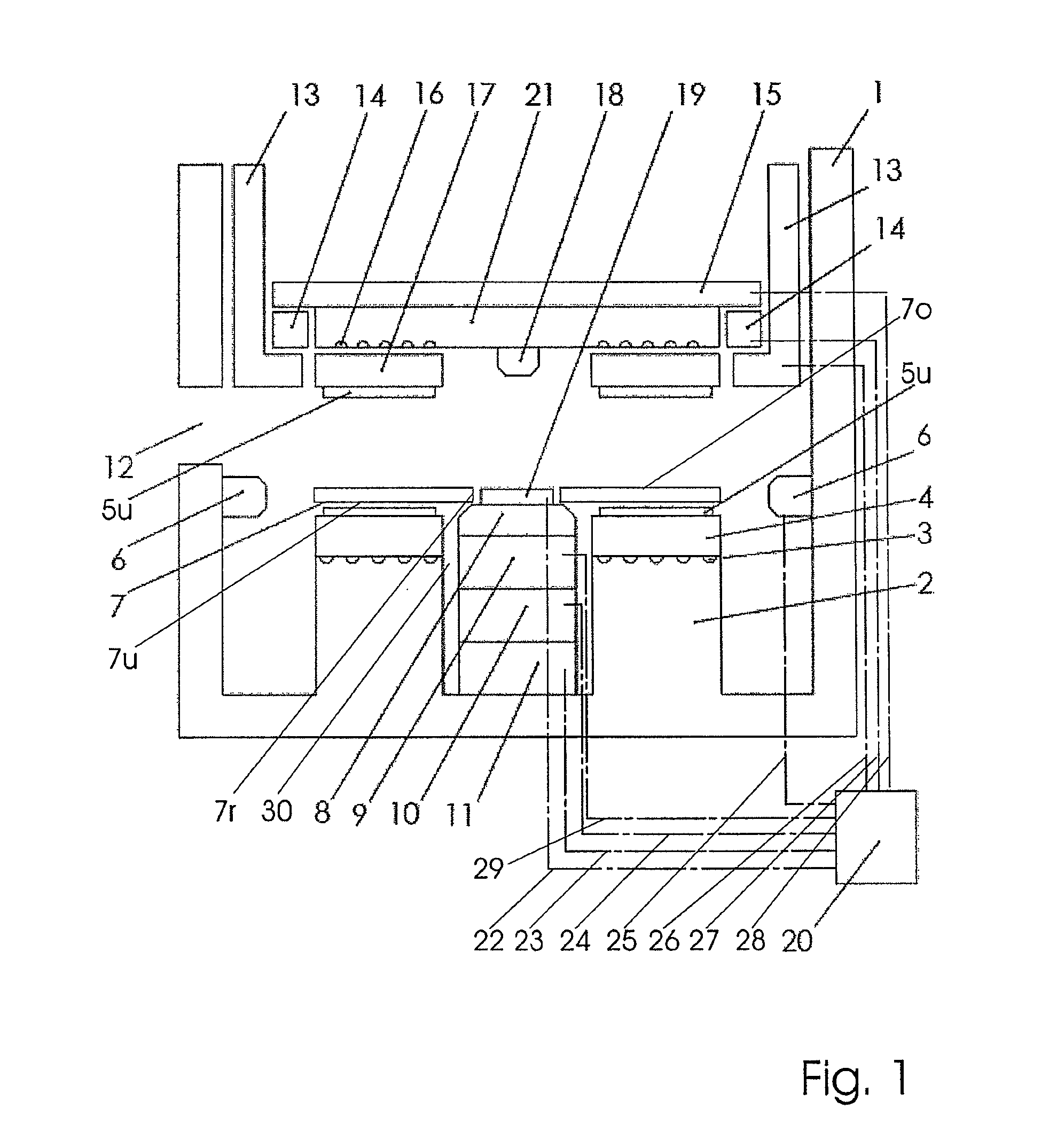
[0026]It is possible to position the upper die precisely relative to the lower die which was previously aligned with the disc due to the fact that the receiving unit comprises markings which can be associated with the exact centre of the disc, and that a detection unit which is fitted to the die receiving unit of the upper die detects the misalignment and / or the spacing of the upper die from the disc as die position information, the die position information being retrievable by the control unit via a line.

Problems solved by technology

When using quartz dies considerable stamping forces are also required, as is a considerable curing time for the material, which considerably restricts throughput when producing the discs and thus causes production costs as well as the production speed to increase considerably.
Further drawbacks of the methods described are the adjustment accuracy of the dies due to the elevated forces to be applied to the disc, as well as problems caused by soiling of the die.

Method used


Image

  • Method and device for producing a nanopatterned disc
  • Method and device for producing a nanopatterned disc
  • Method and device for producing a nanopatterned disc

Examples


Embodiment Construction

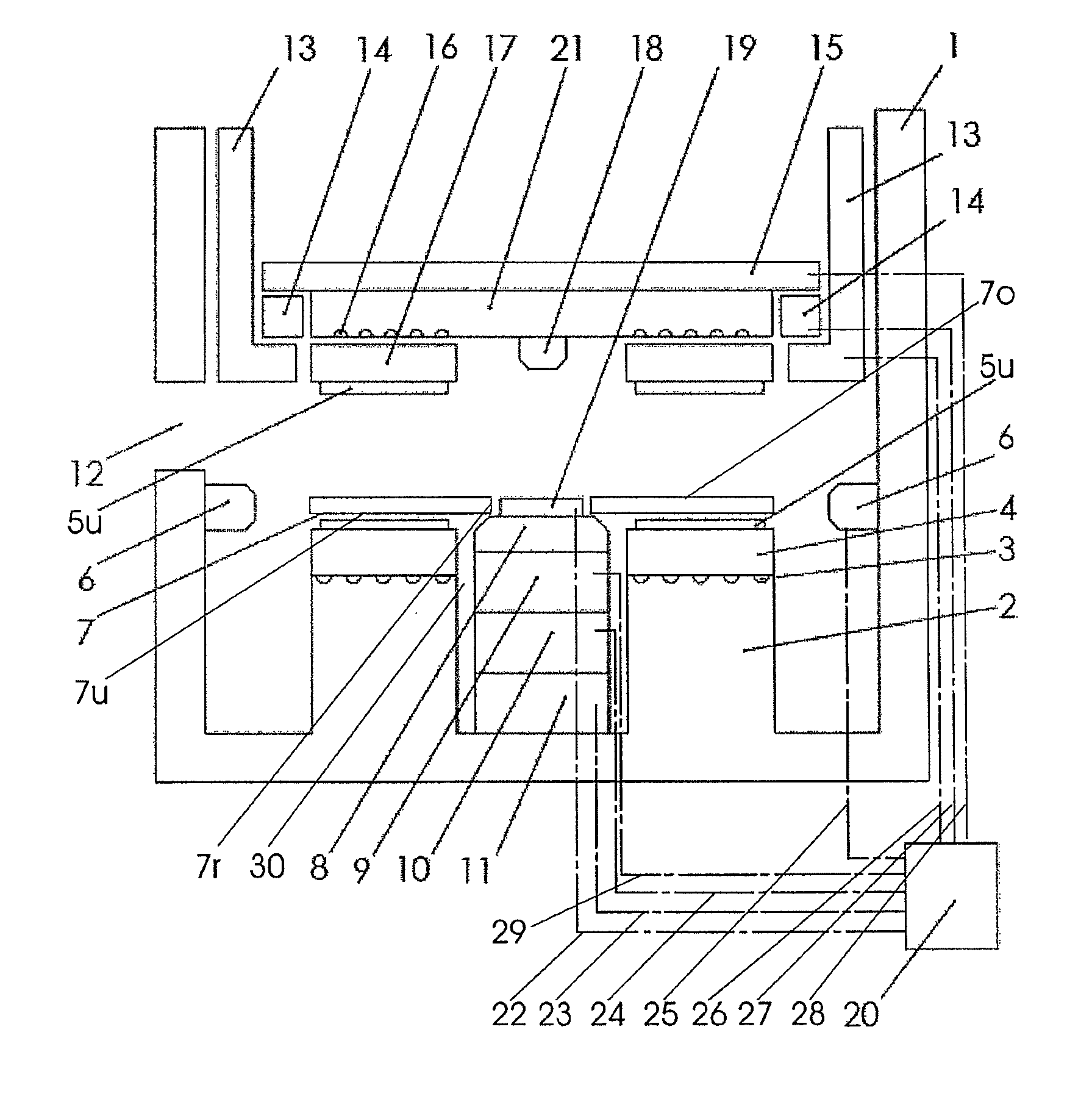
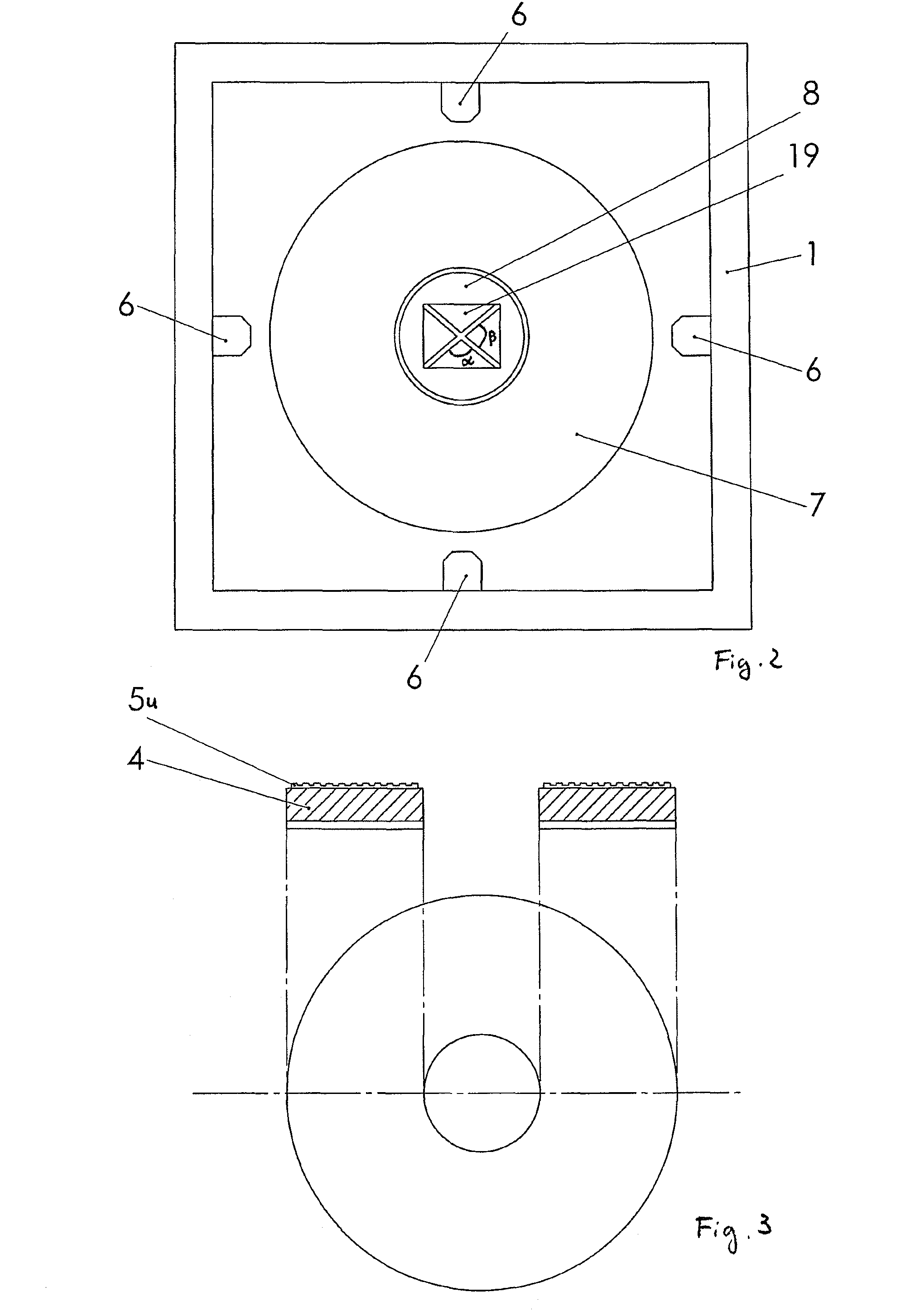
[0037]In the high precision device according to the invention shown in FIG. 1, a housing is denoted with the reference numeral 1 and substantially completely encloses the device. A housing is not necessary. A dimensionally stable connection between the upper and lower die units, for example columns or one-sided support (arms), is instead sufficient. A central control unit 20, which also comprises a data store, a monitor, an entry keyboard and an arithmetic-logic unit, can also be arranged outside the housing 1 and connected to corresponding components of the device via lines 22, 23, 24, 25, 26, 27, 28 and 29.

[0038]On the base of the housing, preferably integral with the housing 1, a die receiving unit 2 as an annular moulding is integrally formed or fitted. From the vacuum grooves 3, via a vacuum line (not shown), which is connected to a vacuum system, a vacuum can be applied to the upper flat side of the die receiving unit 2, by means of which vacuum a die holder 4, which rests on ...


PUM

PropertyMeasurementUnit
rotational speedaaaaaaaaaa
contrastaaaaaaaaaa
compressive forceaaaaaaaaaa

Abstract

The invention relates to a method and a device according to the preambles of claims 1 and 10, and also to the use of a nanopatterned die, a disc with a defined nanopattern and a hard disk drive comprising a disc of this type. In order to propose a more rapidly operating device as well as a corresponding method in which the smallest-possible patterns can be applied to discs, and in order to provide discs, which are produced as cost-effectively as possible, for hard disk drives, said discs having smaller patterns and thus being able to be produced rapidly and cost-effectively, the invention proposes using microcontact printing (μCP) in the production of micropatterned and / or nanopatterned products / substrates of this type.

Description

FIELD OF THE INVENTION[0001]The invention relates to a method and a device according to the preambles of claims 1 and 10 and also to the use of a nanopatterned die, a disc with a defined nanopattern and a hard disk drive with a disc of this type.BACKGROUND OF THE INVENTION[0002]Known hard disk drives consist of one or more discs which are provided with magnetizable material in an annular pattern on one or both flat sides of the discs. Hard disk drives comprise at least one read / write unit in order to read-out the magnetized pattern. At present unpatterned discs are used exclusively.[0003]Due to the increasing demand for ever greater bit density, it is desirable to reduce the dimensions of the magnetizable layer applied to the discs.[0004]Magnetizable patterns for patterned discs (known as “patterned media”) may theoretically also be produced by stamping methods, in which, for example, a robotic arm, generally centrally gripping the centre hole of a disc, places said disc on a die an...

Claims


Application Information

Patent Timeline
Patent Type & Authority Patents(United States)
IPC IPC(8): B29C59/00B29D17/00B29C37/00B81C99/00
CPCB82Y10/00B82Y40/00G03F7/0002
Inventor THALLNER, ERICH
Owner THALLNER ERICH
Learn More