
Elastic wave device using SH waves as the principal component

a technology of elastic wave and principal component, applied in piezoelectric/electrostrictive/magnetostrictive devices, piezoelectric/electrostriction/magnetostriction machines, electrical apparatus, etc., can solve the problems of small insertion loss, boundary acoustic wave, and reduction of polycrystalline silicon thickness, etc., to achieve the effect of reducing spurious components, improving frequency-temperature characteristics, and reducing the spurious componen

Active Publication Date: 2012-03-27
MURATA MFG CO LTD
View PDF20 Cites 8 Cited by
  • Summary
  • Abstract
  • Description
  • Claims
  • Application Information

AI Technical Summary

Benefits of technology

The present invention provides an elastic wave device with a structure that includes a dielectric layer including a SiO2 layer on a piezoelectric body including a LiNbO3 substrate. This device exhibits a good frequency-temperature characteristic and reduces spurious components caused by a higher mode. The device uses an elastic wave whose principal component is an SH wave, and the orientation of the piezoelectric body and the first dielectric layer is important for achieving the desired performance. The device also includes an IDT electrode with a multilayer structure that minimizes unnecessary mode responses and prevents leakage at a fundamental mode. The use of certain dielectric materials and the selection of an appropriate acoustic velocity for the second dielectric layer further enhance the performance of the device. The piezoelectric body has a negative temperature coefficient of resonant frequency (TCF) and the first dielectric layer has a positive TCF, which results in a small absolute value of the TCF and reduces the spurious component caused by a higher mode. Overall, the present invention improves the frequency-temperature characteristic and reduces spurious components caused by a higher mode.

Problems solved by technology

In addition, because the Al layer can be thick, the resistance can be low, and thus the insertion loss can be small.
For the boundary acoustic wave device 1001 described in WO98 / 52279, a boundary acoustic wave propagates while concentrating its energy in the polycrystalline silicon oxide film 1004 between the LiNbO3 substrate 1002 and the polycrystalline silicon film 1005, but there is a problem in that a spurious component caused by a higher mode of the boundary acoustic wave occurs.
However, there is a problem in that a reduction in thickness of the polycrystalline silicon oxide film 1004 leads to an increase in the absolute value of a temperature coefficient of resonant frequency (TCF) of the boundary acoustic wave device 1001.

Method used


Image

  • Elastic wave device using SH waves as the principal component
  • Elastic wave device using SH waves as the principal component
  • Elastic wave device using SH waves as the principal component

Examples


Embodiment Construction

[0050]The present invention is described with respect to specific preferred embodiments thereof below with reference to the drawings.

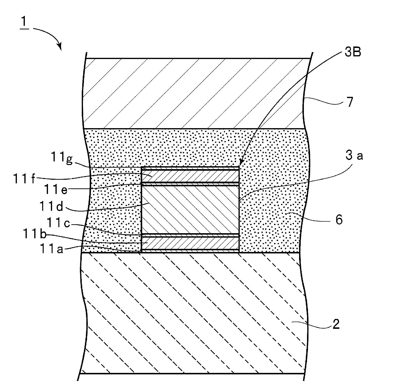
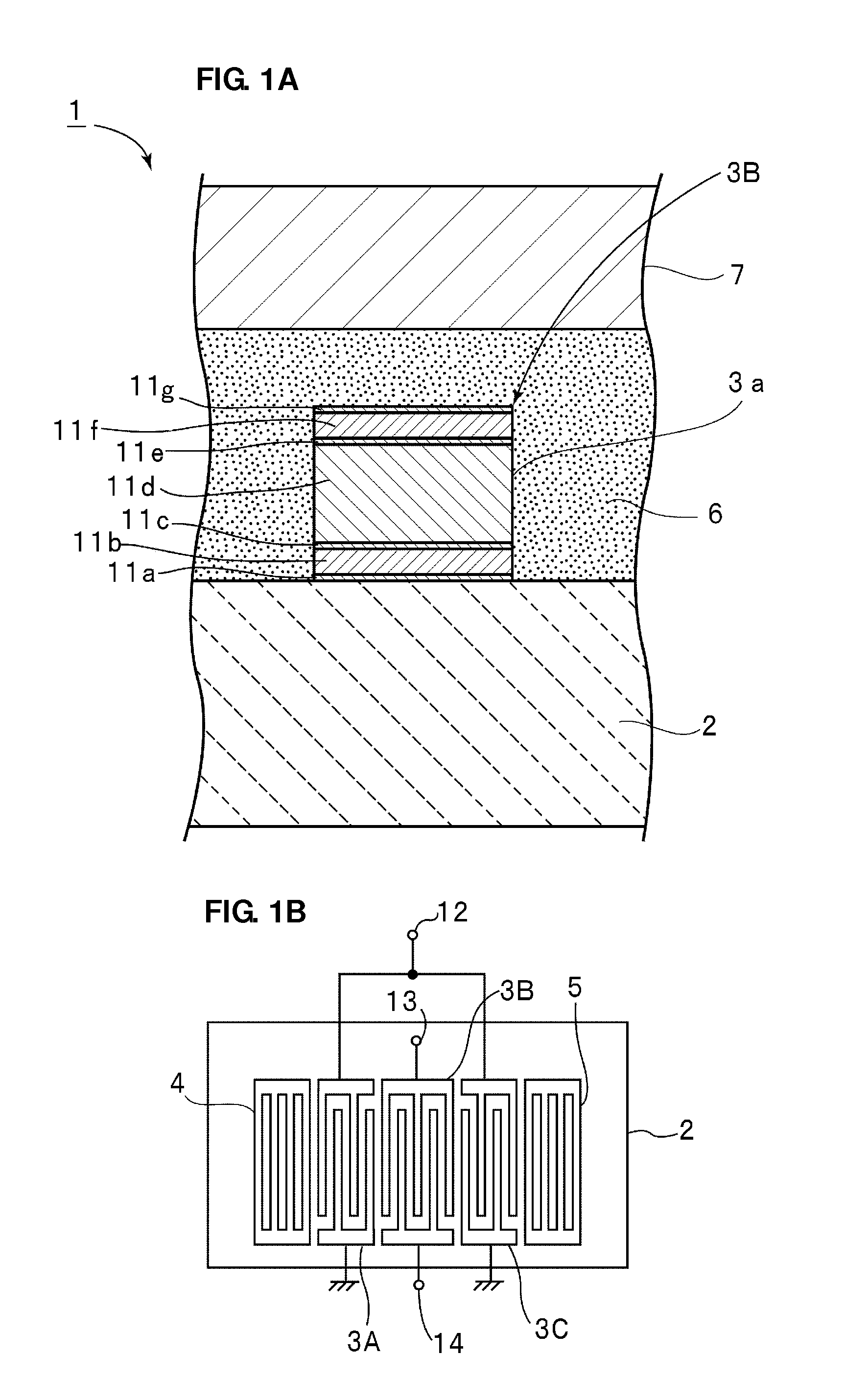
[0051]FIG. 1A is a partially cut-away enlarged front cross-sectional view that illustrates a main portion of a boundary acoustic wave device according to a preferred embodiment of the present invention, and FIG. 1B is a schematic plan view that illustrates an electrode structure of the boundary acoustic wave device.

[0052]A boundary acoustic wave device 1 is a boundary acoustic wave device that uses a boundary acoustic wave whose principal component is an SH wave. It is known that bulk waves propagating through a solid can be classified into three types of longitudinal waves, fast transversal waves, and slow transversal waves, which are called P-waves, SH-waves, and SV-waves, respectively. Among these three types of bulk waves, a bulk wave having the lowest acoustic velocity is a slow transversal wave.

[0053]As illustrated in FIG. 1A, the boundary acoust...


PUM


Abstract

An elastic wave device that achieves an improved frequency-temperature characteristic and a sufficiently reduced spurious component includes a piezoelectric body including a LiNbO3 substrate, a first dielectric layer including a SiO2 layer, a second dielectric layer, and IDT electrodes disposed at an interface between the piezoelectric body and the first dielectric layer. Each of the IDT electrodes includes a multilayer structure in which a first electrode film including at least one layer including Pt or a Pt-based alloy and a second electrode film including Al or an Al-based alloy are provided. φ and θ of Euler angles (φ, θ, ψ) of the LiNbO3 substrate are in the range of φ=0±about 2° and the range of about 80°≦θ≦about 130°, respectively. ψ is in the range of about 5°≦ψ≦about 30°. The normalized thickness h / λ and ψ satisfy the following expression: h / λ×100≦about 0.0019×ψ2+about 0.0115×ψ+3.0.

Description

BACKGROUND OF THE INVENTION[0001]1. Field of the Invention[0002]The present invention relates to an elastic wave device for use in a resonator or a band-pass filter. More specifically, the present invention relates to an elastic wave device that has a structure in which a LiNbO3 substrate is preferably used as a piezoelectric body and a dielectric layer, such as a SiO2 layer, is located on the piezoelectric body.[0003]2. Description of the Related Art[0004]Traditionally, elastic wave devices, such as boundary acoustic wave devices and surface acoustic wave devices, are used in band-pass filters of communication equipment, for example.[0005]One example of this kind of boundary wave device is disclosed in WO98 / 52279 listed below. FIGS. 23 and 24 are a plan view that illustrates a boundary acoustic wave device described in WO98 / 52279 and a schematic partially cut-away front cross-sectional view that illustrates an enlarged main portion thereof, respectively.[0006]A boundary acoustic wa...

Claims


Application Information

Patent Timeline
Patent Type & Authority Patents(United States)
IPC IPC(8): H03H9/25H01L41/187
CPCH03H9/02984H03H9/02559H03H9/0222H03H9/0028H03H9/14541
Inventor NAKAHASHI, NORIHIKO
Owner MURATA MFG CO LTD
Learn More