Resonating element, resonator, electronic device, electronic apparatus, and moving body
a resonator and resonator technology, applied in the direction of oscillator generators, piezoelectric/electrostrictive/magnetostrictive devices, piezoelectric/electrostriction/magnetostriction machines, etc., can solve the problem of inability to obtain desired frequency variable width, inability to achieve versatility of packages, and increase the capacitance ratio of quartz crystal resonators. achieve good frequency-temperature characteristics
- Summary
- Abstract
- Description
- Claims
- Application Information
AI Technical Summary
Benefits of technology
Problems solved by technology
Method used
Image
Examples
modification example 3
of Quartz Crystal Resonating Element
[0129]FIGS. 14A and 14B show a modification example of the quartz crystal resonating element, in which FIG. 14A is a schematic plan view when a structure of the quartz crystal resonating element according to the fourth embodiment of the invention is viewed from the top, and FIG. 14B is a cross-sectional view taken along the line J-J of FIG. 14A.
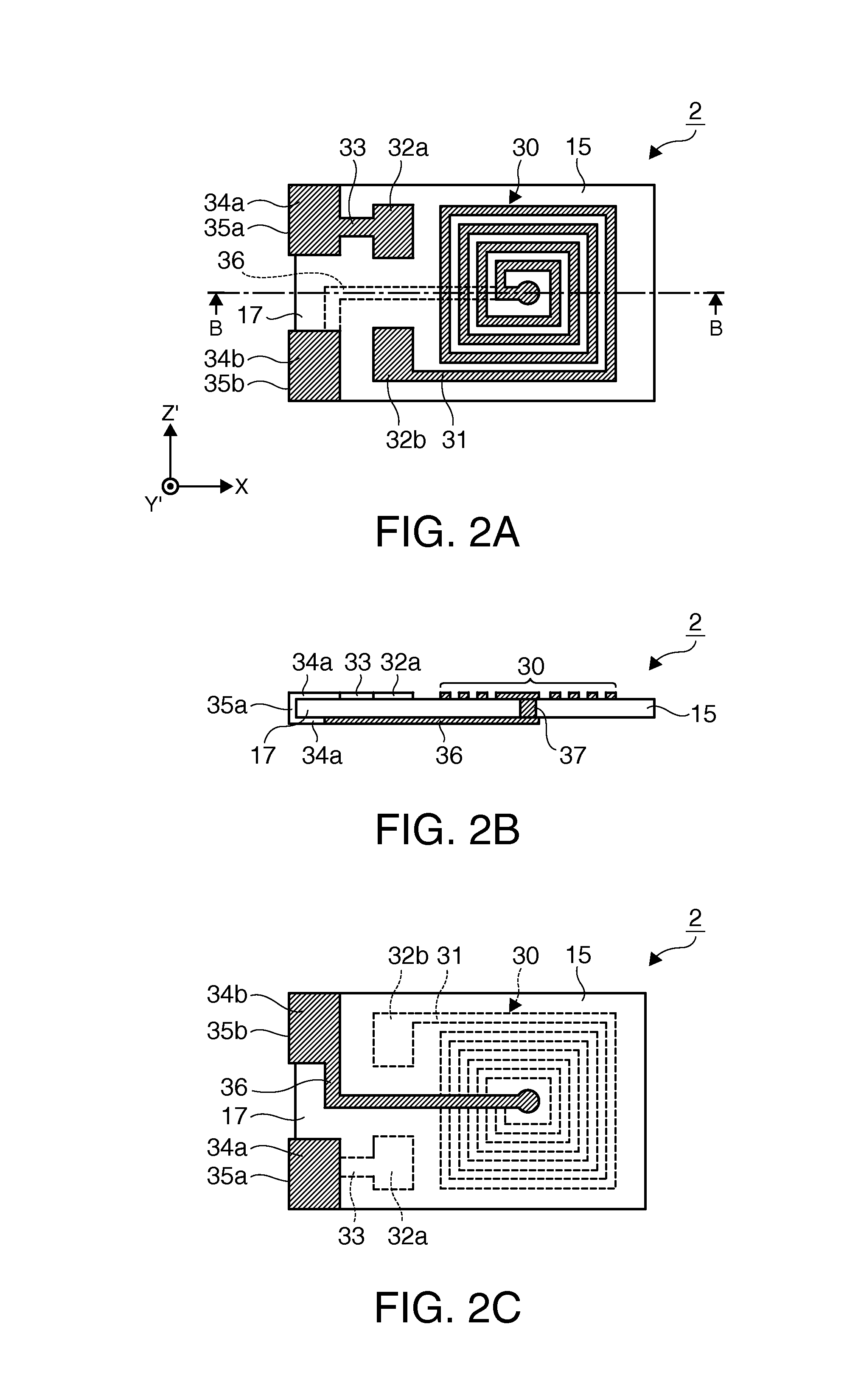
[0130]As shown in FIGS. 14A and 14B, a quartz crystal resonating element 303 according to the present modification example is formed by mounting the quartz crystal resonator element 1 on the intermediate substrate 302 which is a modification example of the intermediate substrate 2 of the embodiment shown in FIGS. 2A to 2C. The terminals 332a and 332b for joining to the quartz crystal resonator element 1 provided on one main surface of the intermediate substrate 302 are aligned with the corresponding external connection terminals 22a and 22b of the quartz crystal resonator element 1 and are joined thereto vi...
modification example 1
of Quartz Crystal Resonator Element
[0140]FIGS. 16A and 16B show a modification example of the quartz crystal resonator element, in which FIG. 16A is a schematic plan view when a structure of a quartz crystal resonator element according to a fifth embodiment of the invention is viewed from the top, and FIG. 16B is a cross-sectional view taken along the line L-L of FIG. 16A.
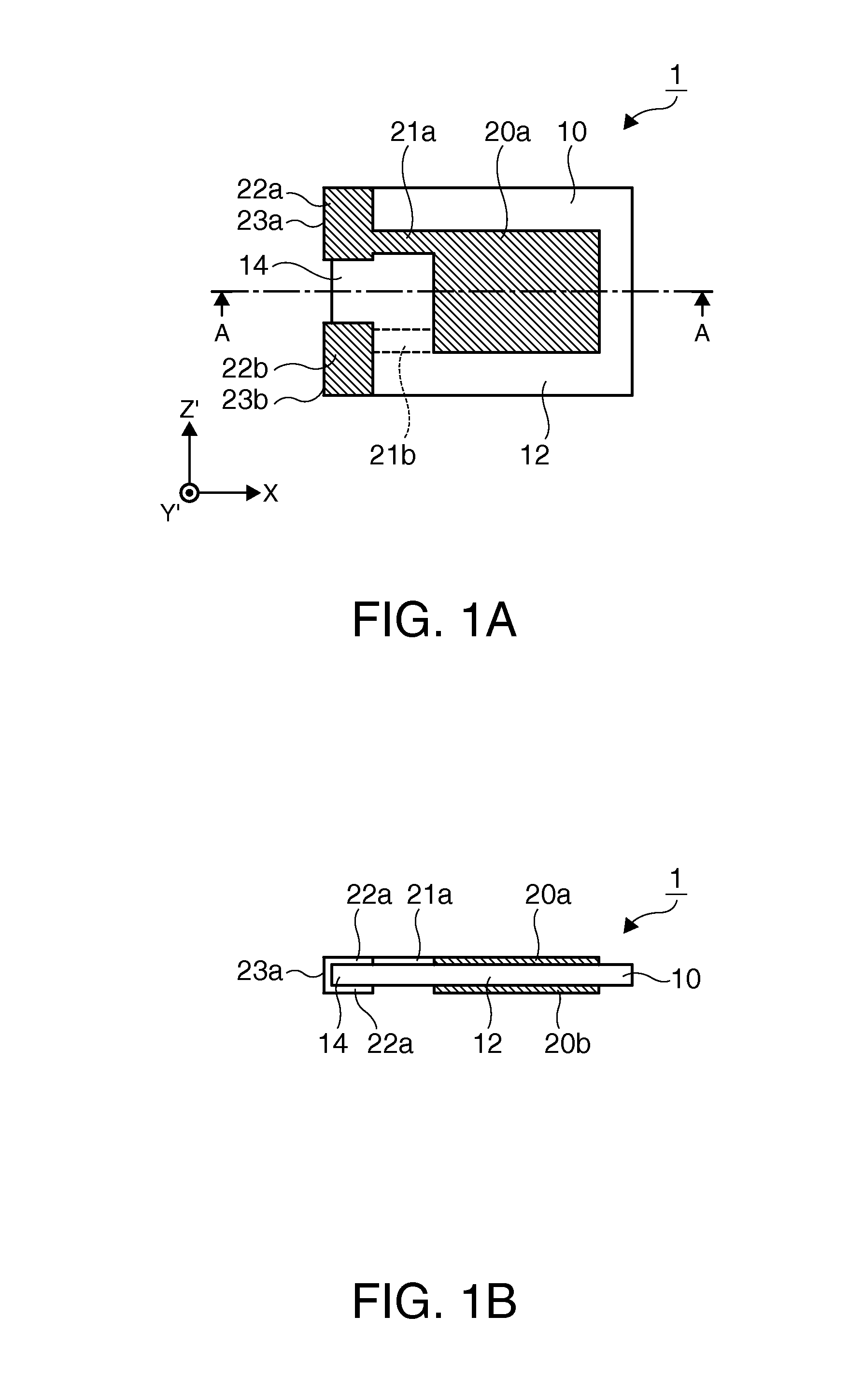
[0141]A quartz crystal resonator element 101 which is a modification example of the quartz crystal resonator element 1 of the embodiment shown in FIGS. 1A and 1B includes, as shown in FIG. 16A, a quartz crystal substrate 110, excitation electrodes 120a and 120b, and external connection terminals 122a and 122b. The quartz crystal substrate 110 includes a support portion 114 which is a fixed end and a vibrating portion 112 which is a free end. Here, the vibrating portion 112 according to the present modification example indicates a region which is interposed between mesa portions 116 formed on both main surfaces of t...
modification example 4
of Quartz Crystal Resonating Element
[0143]FIGS. 17A and 17B show a modification example of the quartz crystal resonating element, in which FIG. 17A is a schematic plan view when a structure of the quartz crystal resonating element according to the fifth embodiment of the invention is viewed from the top, and FIG. 17B is a cross-sectional view taken along the line M-M of FIG. 17A.
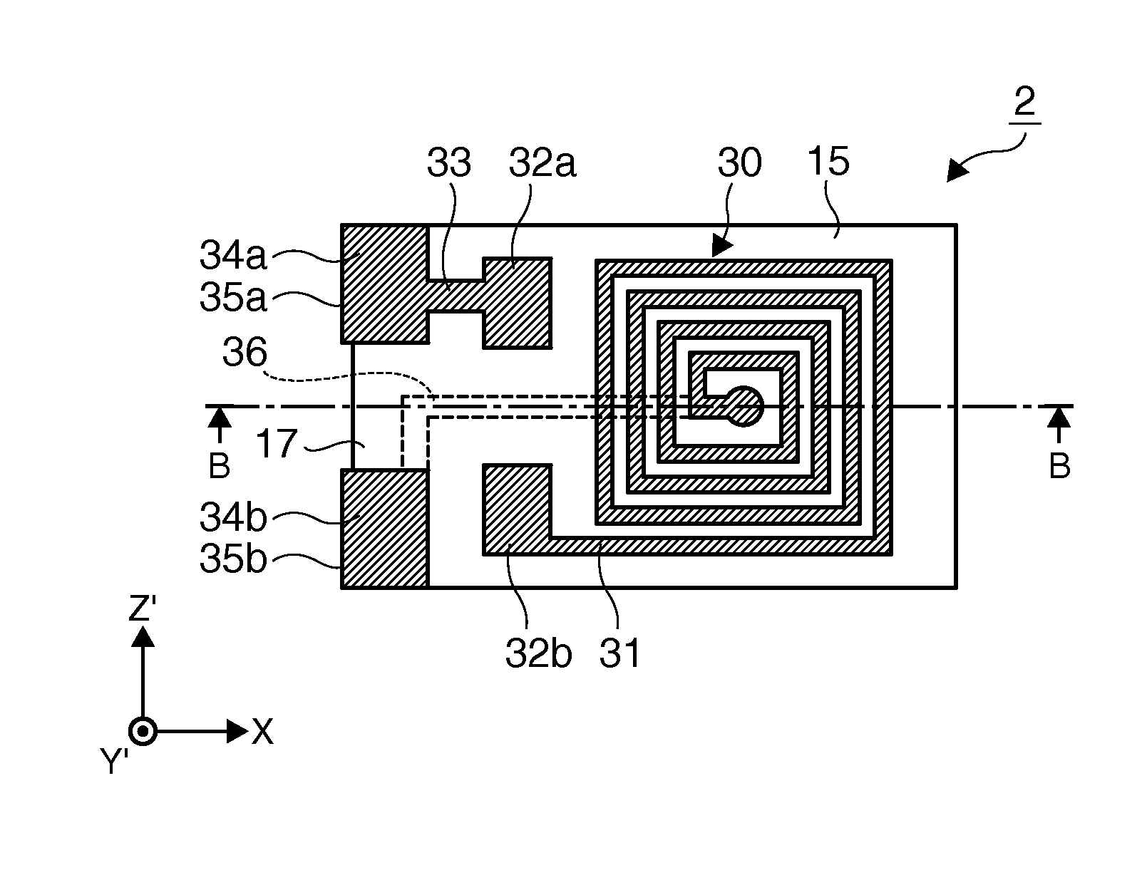
[0144]As shown in FIGS. 17A and 17B, a quartz crystal resonating element 304 according to the present modification example is formed by mounting a quartz crystal resonator element 101 which is a modification example of the quartz crystal resonator element 1 of the embodiment shown in FIGS. 1A and 1B on the intermediate substrate 2. The terminals 32a and 32b for joining to the quartz crystal resonator element 101 provided on one main surface of the intermediate substrate 2 are aligned with the corresponding external connection terminals 122a and 122b of the quartz crystal resonator element 101 and are joined ...
PUM
 Abstract
Description
Claims
Application Information
 - R&D
- Intellectual Property
- Life Sciences
- Materials
- Tech Scout
- Unparalleled Data Quality
- Higher Quality Content
- 60% Fewer Hallucinations
Browse by: Latest US Patents, China's latest patents, Technical Efficacy Thesaurus, Application Domain, Technology Topic, Popular Technical Reports.
© 2025 PatSnap. All rights reserved.Legal|Privacy policy|Modern Slavery Act Transparency Statement|Sitemap|About US| Contact US: help@patsnap.com


