Flexible circuit electrode array device and a method for backside processing of a flexible circuit electrode device

a flexible circuit electrode and array device technology, applied in the field of neural stimulation, can solve the problems of array not being in good contact with retina tissue, not producing adequate simulated vision to truly aid the visually impaired, and dragging from the retina,

Active Publication Date: 2012-03-27
CORTIGENT INC
View PDF9 Cites 68 Cited by
  • Summary
  • Abstract
  • Description
  • Claims
  • Application Information

AI Technical Summary

Benefits of technology

[0021]The purpose of backside processing of a polyimide device is to expose conductors on the other side of the polyimide device so that conductors on both sides are opened to meet special geometry requirement of the device. Both sides of electrodes on an electrode array have to be open so that one side can be attached to retina and the other side to the bond pads of the electronic package. The advantage is that the device does not have to be folded when implanted because the electrode array is on the opposite side of the bond pads of the electronic package.
[0022]The invention involves several processes to achieve a flexible electrode array manufactured by a backside processing method. The approaches underlined are designed so that the proposed processes are to be compatible with current thin film electrode array thin film electrode array. The process can be implemented as a clean process without introducing any undesirable residue or hazardous material.

Problems solved by technology

While some of these early attempts met with some limited success, these early prosthetic devices were large, bulky and could not produce adequate simulated vision to truly aid the visually impaired.
If an electrode array is placed on the surface of the tissue being stimulated without a ready method of confinement the array may not be in good contact with the retina tissue, or it drifts away from the retina.
As a result, there may not be enough current density passing through the neuronal cells in the retina tissue to cause a response, or the response may change when the array is moved.
However, if the active electrodes are lifted from the tissue surface, the responses elicited by the stimulation of the individual electrodes may not be differentiable or distinctive because of the diffusive current paths from the lifted electrodes, resulting great reduction of effective resolution for percepts.
This sub-retina approach presents significant surgical difficultness when the device and array are implanted.

Method used


Image

  • Flexible circuit electrode array device and a method for backside processing of a flexible circuit electrode device
  • Flexible circuit electrode array device and a method for backside processing of a flexible circuit electrode device
  • Flexible circuit electrode array device and a method for backside processing of a flexible circuit electrode device

Examples


Embodiment Construction

[0071]The following description is of the best mode presently contemplated for carrying out the invention. This description is not to be taken in a limiting sense, but is made merely for the purpose of describing the general principles of the invention. The scope of the invention should be determined with reference to the claims.

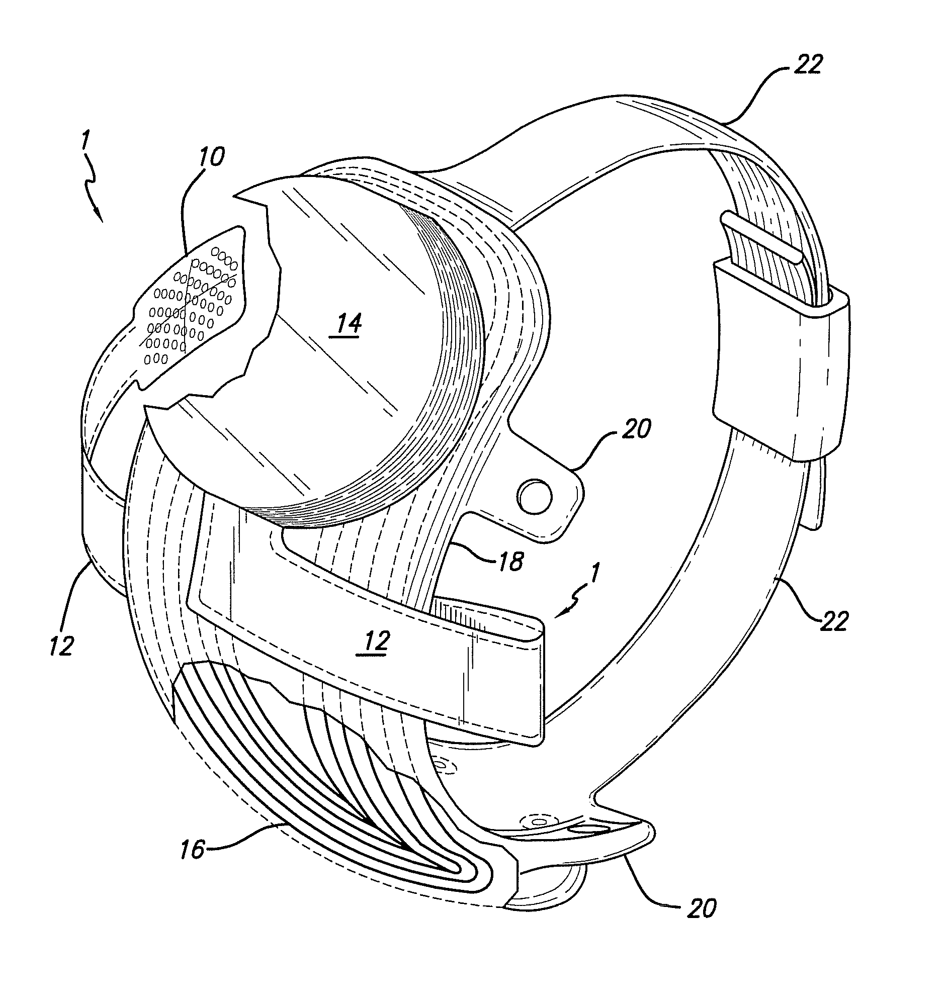
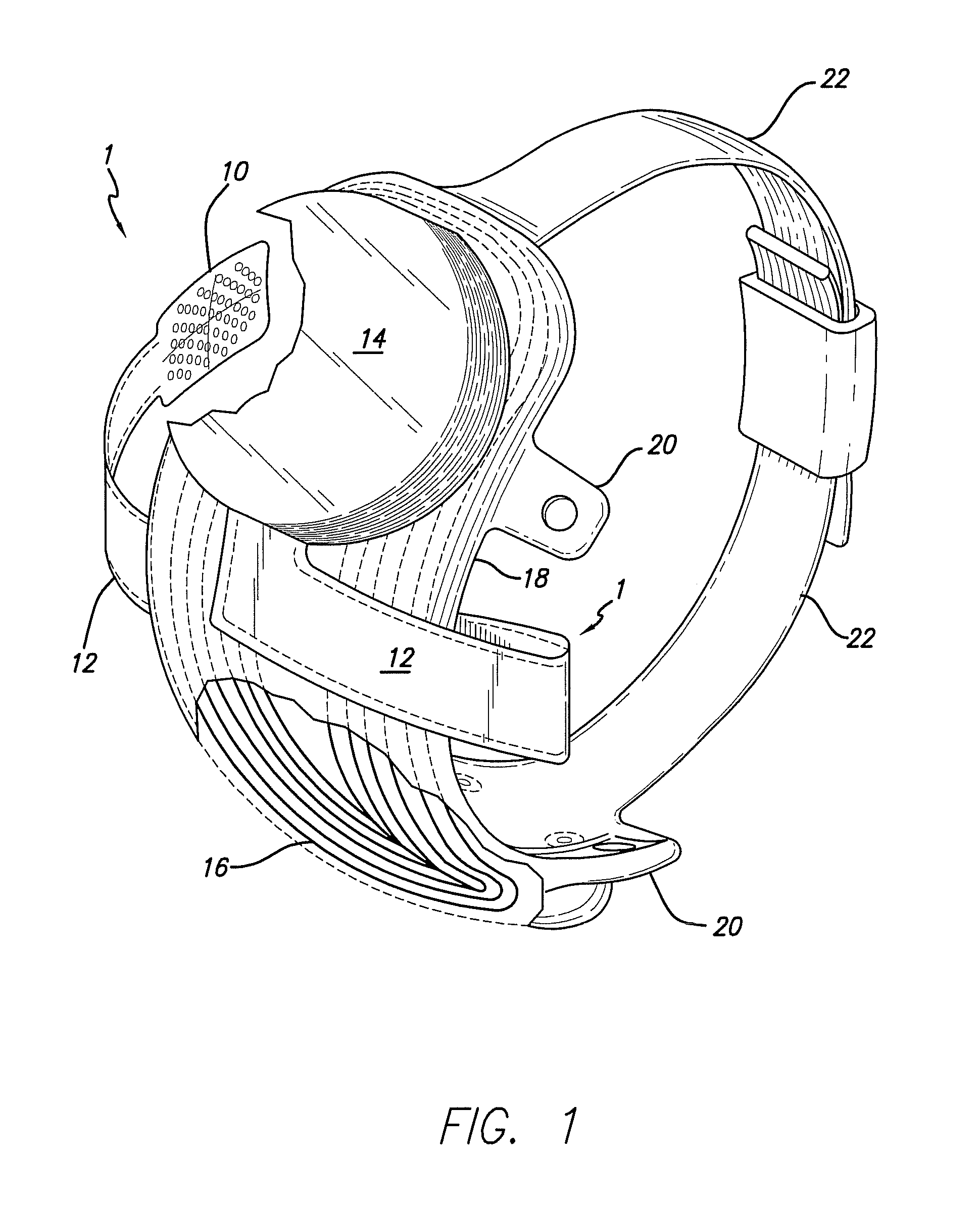
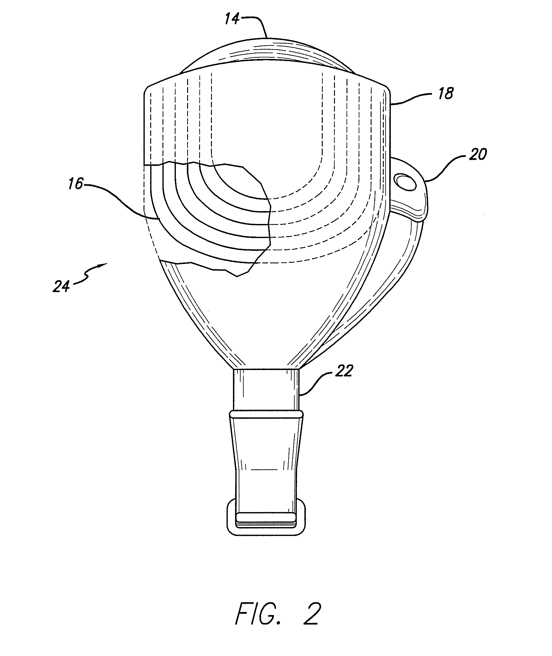
[0072]FIG. 1 shows a perspective view of the implanted portion of the preferred retinal prosthesis. A flexible circuit 1 includes a flexible circuit electrode array 10 which is mounted by a retinal tack (not shown) or similar means to the epiretinal surface. The flexible circuit electrode array 10 is electrically coupled by a flexible circuit cable 12, which pierces the sclera and is electrically coupled to an electronics package 14, external to the sclera.

[0073]The electronics package 14 is electrically coupled to a secondary inductive coil 16. Preferably the secondary inductive coil 16 is made from wound wire. Alternatively, the secondary inductive coil 16...


PUM

PropertyMeasurementUnit
angleaaaaaaaaaa
angleaaaaaaaaaa
angleaaaaaaaaaa

Abstract

The invention involves a flexible circuit electrode array device comprising: a polymer layer; wherein the polymer layer includes one or more metal traces, an electrode array; one or more bond pads; and the electrode array is located on the opposite side of the polymer layer.The invention further involves a method for backside processing of a flexible circuit electrode device, comprising: applying polymer film on a substrate; processing the front side; releasing the polymer film from substrate; flipping over the polymer film and fixing it onto the substrate; processing the backside; and final releasing of the polymer film from the substrate.The invention further involves a method for backside processing of a flexible circuit electrode device, comprising: processing the front side without releasing the polymer; processing the backside by sacrificial substrate method, or by laser drilling method; and releasing the polymer film from the substrate.

Description

CROSS-REFERENCE TO RELATED APPLICATIONS[0001]This application claims the benefit of U.S. Provisional Application No. 60 / 950,754, “Method for Backside Processing of a Polyimide Device”, filed Jul. 19, 2007 and U.S. Provisional Application No. 60 / 971,173, “Method for Backside Processing of a Polyimide Device”, filed Sep. 10, 2007, the disclosure of each is incorporated herein by reference.GOVERNMENT RIGHTS NOTICE[0002]This invention was made with government support under grant No. R24EY12893-01, awarded by the National Institutes of Health. The government has certain rights in the invention.FIELD OF THE INVENTION[0003]The present invention is generally directed to neural stimulation and more specifically to an improved electrode array for neural stimulation. The present invention is more specifically directed to a method for backside processing of a flexible circuit electrode array device and an improved electrode array device achieved by the process of backside processing.BACKGROUND ...

Claims


Application Information

Patent Timeline
Patent Type & Authority Patents(United States)
IPC IPC(8): A61N1/04
CPCA61N1/0543B23K26/365A61N1/0541A61N1/05B23K26/361B23K26/362
Inventor YAO, QINGFANGNEYSMITH, JORDAN MATTHEWTALBOT, NEIL HAMILTONLITTLE, JAMES SINGLETONGREENBERG, ROBERT J.
Owner CORTIGENT INC
Why Eureka
Try Eureka