Valve guide and spring retainer assemblies

a technology of valve guide and spring retainer, which is applied in the direction of machines/engines, liquid fuel engines, positive displacement liquid engines, etc., can solve the problems of y-block design, no commercial success, and individual bores in the plunger pump housing are subject to fatigue, so as to achieve the effect of convenient insertion and removal

Inactive Publication Date: 2012-04-03
ALTIS INVESTMENTS LLC
View PDF26 Cites 38 Cited by
  • Summary
  • Abstract
  • Description
  • Claims
  • Application Information

AI Technical Summary

Benefits of technology

[0016]The present invention includes improved valve guide and spring retainer assemblies for use in plunger pump housings having an outwardly flared transition area in the suction bore. Alternative valve guide and spring retainer assemblies of the present invention are for use in plunger pump housings having an outwardly flared transition area in the discharge bore as well as the suction bore. Note that an outwardly flared transition area in the suction bore (together with an outwardly flared transition area in the discharge bore in alternative embodiments) allows relatively easier insertion and removal of portions of improved valve guides and spring retainer assemblies in these areas.
[0021]Field maintenance is facilitated for pumps incorporating the plunger pump housings and improved valve guide and spring retainer assemblies of the present invention. Specifically, the requirement for maintaining precise alignment as to rotation and angle of entry during insertion and removal of the DVLSG-II, the TDBS and / or the SVTSG-SR-II is relaxed. Additionally, one or more O-rings on an SVTSG-SR-II, a DVLSG-II or a TDBS can assist in retaining these structures temporarily in their respective outwardly flared bore transition areas during pump assembly. And O-rings on an SVTSG-SR-II have a self-centering function that makes the use of top-stem-guided suction valves more efficient and practical.
[0026]An alternative illustrated embodiment of a plunger pump housing of the present invention comprises a discharge bore comprising a portion with substantially circular cross-sections and a second centerline for accommodating, e.g., a circular discharge valve seat, followed by a transition area that is not necessarily outwardly flared. Note that the first and second centerlines are colinear, and that a discharge bore shoulder may be either present or absent. If the discharge bore shoulder is absent in this embodiment, stress in the pump housing is thereby reduced.
[0028]Illustrated embodiments of plunger pump housings of the present invention further comprise an access bore comprising a distal retainer portion with substantially circular cross-sections and a fourth center line. The distal retainer portion accommodates an access bore plug retainer and is followed by a proximal transition area having elongated cross-sections that can be sealed with a removable (flanged or flangeless) access bore plug. An access bore shoulder is located between the distal retainer portion and the proximal transition area. Removal of the access bore plug facilitates access to interior portions of the plunger pump housing. The access bore proximal transition area may be cylindrical or, in alternative embodiments, it may be inwardly flared (i.e., the proximal transition area may have a first predetermined inward taper extending from the access bore shoulder). Removal and replacement of an access bore plug having a peripheral inward taper corresponding to the first predetermined inward taper of such an access bore transition area is easier than performing these operations with a cylindrical access bore plug in a cylindrical access bore transition area. However, maintenance of precise alignment as to rotation and angle of entry or removal of such a cylindrical access bore plug can still be achieved during routine maintenance because of the relatively exposed location of the access bore plug. Thus, the choice of a cylindrical or tapered configuration for an access bore plug and a corresponding access bore transition area may additionally involve considerations such as the cost of machining these structures. Note that as further described below, one illustrated embodiment of a flanged access bore side spacer-plug has an integral flange (which bears on the access bore shoulder) and at least one integral side spacer, whereas an alternative illustrated embodiment of a flangeless access bore plug has neither an integral flange nor an integral side spacer. The access bore's fourth centerline is colinear with the third centerline.
[0037]Simultaneous with this transmission of suction valve spring force, self-centering of the DVLSG-II (or the TDBS) and the SVTSG-SR-II (or SVSR) will occur. Such self-centering is facilitated by one or more O-rings in peripheral O-ring grooves. These O-rings and grooves are dimensioned to allow an increasingly close sliding fit as the DVLSG-II (or the TDBS) and the SVTSG-SR-II (or SVSR) are accommodated within their respective outwardly flared transition areas. Such accommodation is achieved when, for example, the first predetermined outward taper of the suction bore transition area is equal to or slightly greater than the fifth predetermined peripheral outward taper of the SVTSG-SR-II (or SVSR). Similarly, such accommodation is achieved when, for example, the second predetermined outward taper of the discharge bore transition area is equal to or slightly greater than the third predetermined peripheral outward taper of the DVLSG-SR or the fourth predetermined peripheral outward taper of the TDBS. As the O-rings contact the respective outwardly flared transition areas, further insertion is resisted due to increasing compression of the O-rings. Because such O-ring compression occurs substantially equally along each O-ring periphery, the resulting peripheral compressive forces tend to self-center the DVLSG-II (or the TDBS), as well as the SVTSG-SR-II (or SVSR) within their respective outwardly flared transition areas. Because of the resilience of the O-rings, this self-centering function is effective over a small range of longitudinal, lateral and angular movement within each outwardly flared transition area. Thus, the DVLSG-II (or the TDBS) and the SVTSG-SR-II (or SVSR) can move slightly to accommodate small misalignments of the discharge and suction valve bodies and / or small misalignments of valve guide stems (due, e.g., to manufacturing tolerances). Note also that each side spacer may be dimensioned to fit closely between the plunger pump housing and a plunger inserted for use within the housing. By decreasing the amount of internal pump space that is not swept by the plunger, such close fitting of each side spacer can improve a pump's volumetric efficiency.

Problems solved by technology

Each individual bore in a plunger pump housing is subject to fatigue due to alternating high and low pressures which occur with each stroke of the plunger cycle.
Although several variations of the Y-block design have been evaluated, none have become commercially successful for several reasons.
One reason is that mechanics find field maintenance on Y-block fluid sections difficult.
For example, replacement of plungers and / or plunger packing is significantly more complicated in Y-block designs than in the earlier designs represented by FIG. 1.
This operation, which would leave the plunger packing easily accessible from the proximal end of the plunger bore, is impossible in a Y-block design.
Thus the Y-block configuration, while reducing stress in plunger pump housings relative to earlier designs, is associated with significant disadvantages.
Conventional valve designs incorporating secure placement of guides for both top and lower valve guide stems have been associated with complex components and difficult maintenance.
Such precise alignment may be difficult to maintain during field service operations.

Method used


Image

  • Valve guide and spring retainer assemblies
  • Valve guide and spring retainer assemblies
  • Valve guide and spring retainer assemblies

Examples


Embodiment Construction

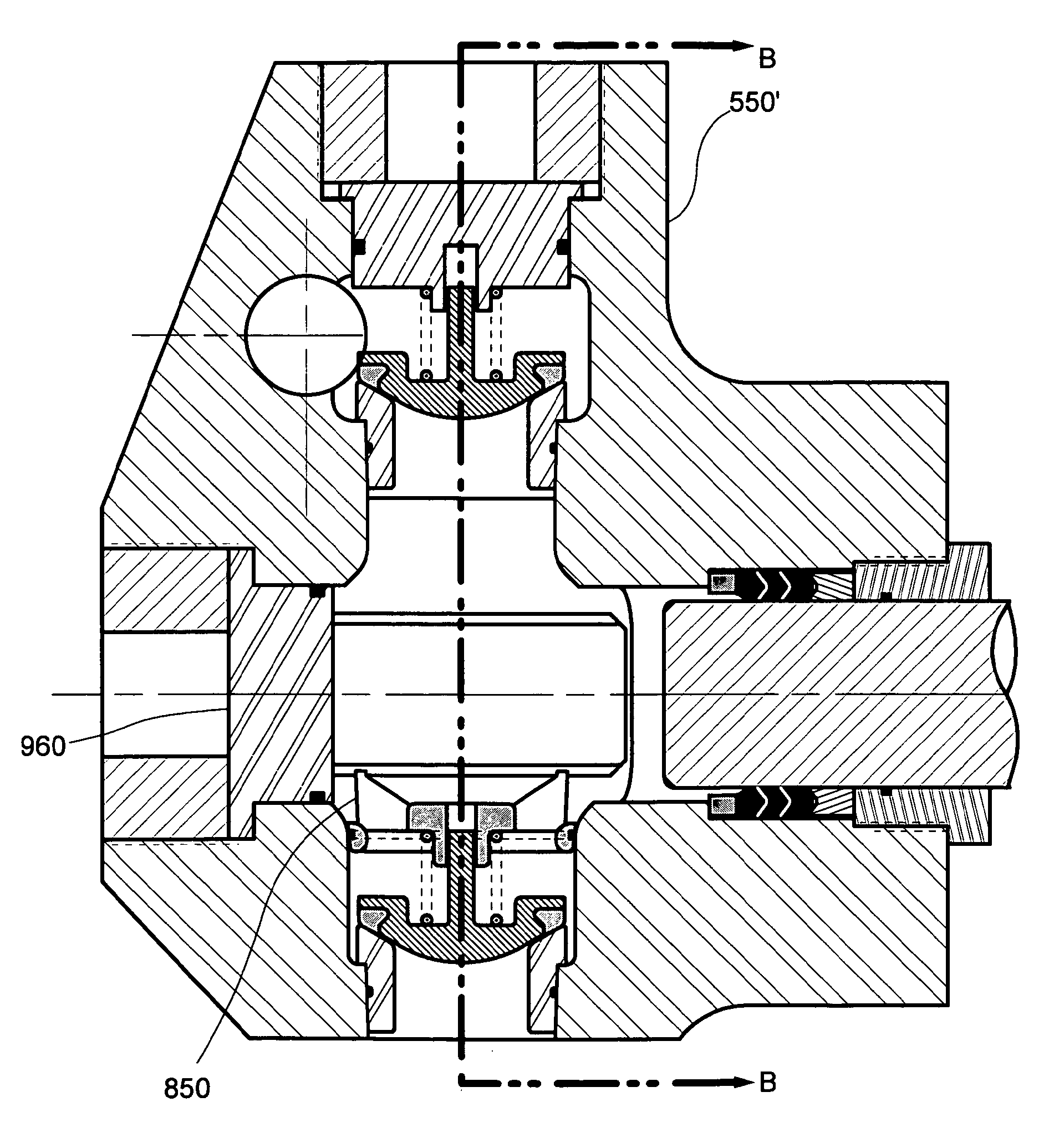
[0081]FIG. 7A schematically illustrates cross-sections of a right-angular pump housing 550 of the present invention, including a suction bore 510 having a first centerline and comprising a first portion 512 with substantially circular cross-sections followed a second portion. The second portion of suction bore 510 comprises a cylindrical area 518 followed by an outwardly flared transition area 514. There is a suction bore shoulder 516 between first portion 512 and cylindrical area 518.

[0082]Continuing with FIG. 7A, a discharge bore 520 comprises a first portion 522 with substantially circular cross-sections, a second portion comprising an outwardly flared transition area 524, a discharge bore shoulder 526 between the first and second portions, and a second centerline, the first and second centerlines being colinear.

[0083]Continuing with FIG. 7A, a plunger bore 530 comprises a proximal packing area 532 having substantially circular cross-sections, a distal transition area 534, a plun...


PUM


Abstract

Tapered valve guide and spring retainer assemblies are described for use in plunger pump housings that incorporate corresponding outwardly flared discharge and suction bores, as well as structural features for stress-relief. Plunger pumps so constructed are relatively resistant to fatigue failure because of stress reductions, and they may incorporate a variety of valve styles, including top and lower stem-guided valves and crow-foot-guided valves, in easily-maintained configurations. Besides forming a part of valve guide and spring retainer assemblies, side spacers may be shaped and dimensioned to improve volumetric efficiency of the pumps in which they are used.

Description

[0001]This is a continuation-in-part application (CIP) of U.S. patent application Ser. No. 11 / 125,282 filed May 9, 2005, which was a CIP of U.S. patent application Ser. No. 10 / 613,295 (now U.S. Pat. No. 6,910,871), which was a CIP of U.S. patent application Ser. No. 10 / 288,706 (now U.S. Pat. No. 6,623,259), which was a CIP of U.S. patent application Ser. No. 10 / 139,770 (now U.S. Pat. No. 6,544,012), which was a CIP of U.S. patent application Ser. No. 09 / 618,693 (now U.S. Pat. No. 6,382,940).FIELD OF THE INVENTION[0002]The invention relates generally to high-pressure plunger pumps used, for example, in oil field operations. More particularly, the invention relates to valve guides and spring retainers for use in plunger pump housings that incorporate structural features for stress-relief and for accommodating valve guide and / or spring retainer assemblies.BACKGROUND[0003]Engineers typically design high-pressure oil field plunger pumps in two sections; the (proximal) power section and t...

Claims


Application Information

Patent Timeline
Patent Type & Authority Patents(United States)
IPC IPC(8): F04B39/10
CPCF04B53/007F04B53/164F04B53/16F04B53/1032Y10T137/7838
Inventor BLUME, GEORGE H.
Owner ALTIS INVESTMENTS LLC
Why Eureka
Try Eureka