Heat exchanger for medical use and artificial heart-lung machine

a technology of heat exchanger and medical device, applied in the field of heat exchanger, to achieve the effect of sufficient heat exchange performance and sufficient air removal performan

Inactive Publication Date: 2012-04-03
JMS CO LTD
View PDF13 Cites 2 Cited by
  • Summary
  • Abstract
  • Description
  • Claims
  • Application Information

AI Technical Summary

Benefits of technology

[0024]The heat exchanger for medical use having the above-described configuration can release air within the heat exchanger and air mixed in a fluid (e.g., blood) to be subjected to heat exchange to the outside by means of the hollow fiber membrane provided on at least one of the entrance side and the exit side of the blood channel. As a result, sufficient air-removal performance can be obtained while maintaining sufficient heat-exchange performance, and there is no need to swirl the fluid to be subjected to heat exchange.

Problems solved by technology

However, even when priming has been performed, air may mix into the blood during the blood circulation, and so it is required to equip the artificial heart-lung machine with a function for removing air.

Method used


Image

  • Heat exchanger for medical use and artificial heart-lung machine
  • Heat exchanger for medical use and artificial heart-lung machine
  • Heat exchanger for medical use and artificial heart-lung machine

Examples


embodiment 1

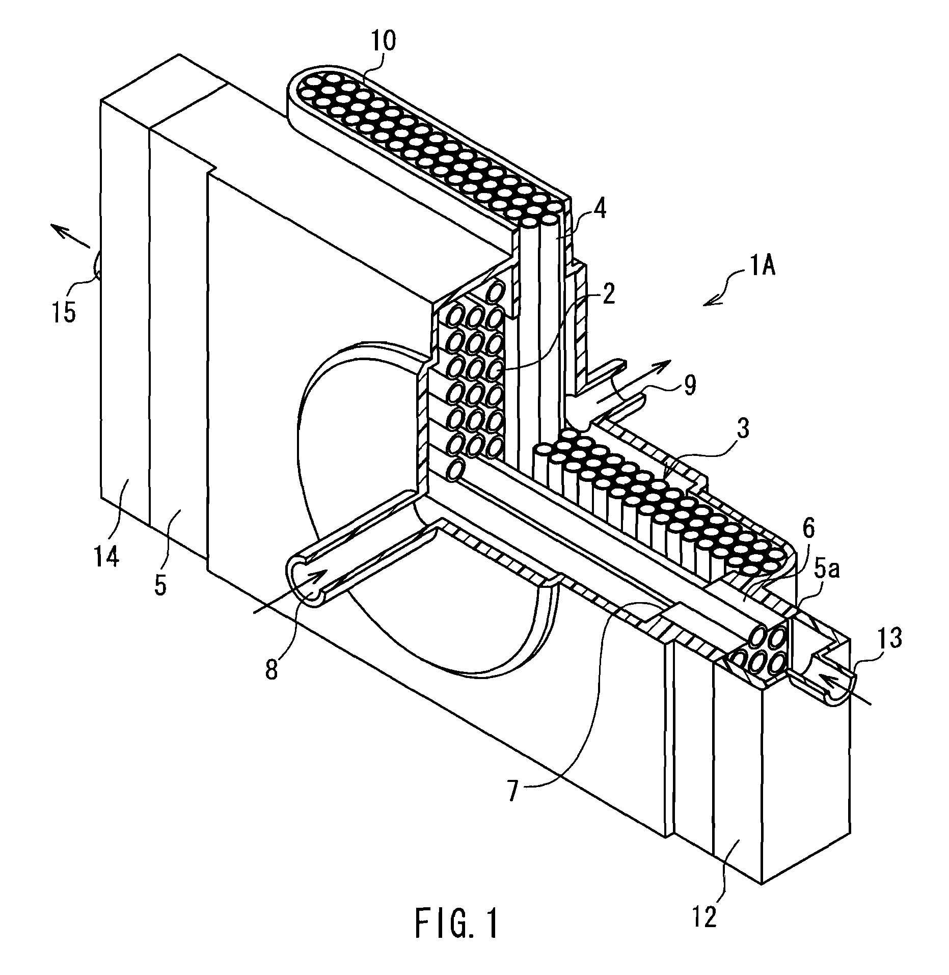
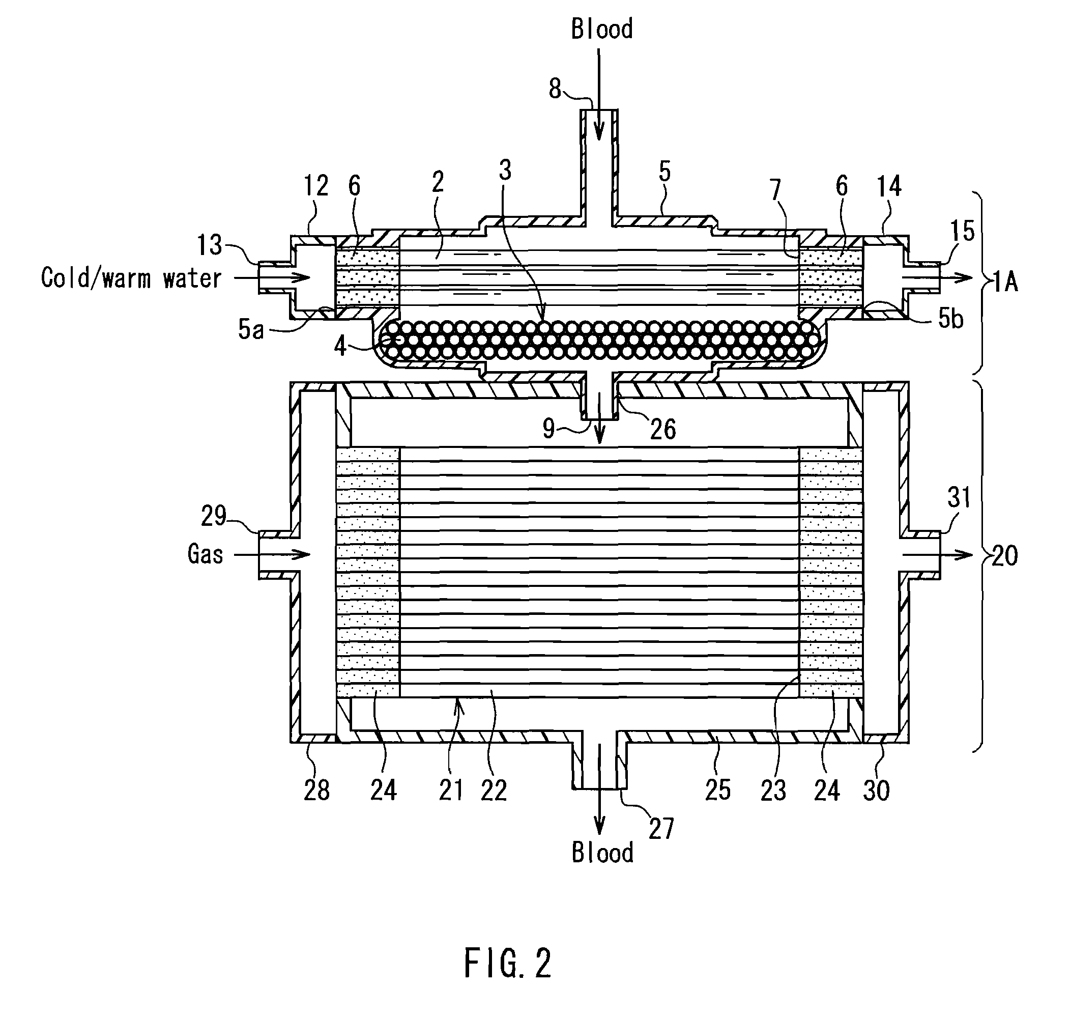
[0086]The configurations of a heat exchanger for medical use and an artificial heart-lung machine according to Embodiment 1 of the present invention will be described using FIGS. 1 and 2. FIG. 1 is a perspective view schematically showing the configuration of a heat exchanger 1A of the present embodiment. FIG. 2 is cross-sectional view schematically showing the configuration of an artificial heart-lung machine including the heat exchanger 1A of the present embodiment.

[0087]In FIG. 1, the heat exchanger 1A is shown partially sectioned. The heat exchanger 1A shown in FIG. 1 is used to control the temperature of blood removed from a patient and functions as a heat-exchanging portion of the artificial heart-lung machine shown in FIG. 2.

[0088]As shown in FIGS. 1 and 2, the heat exchanger 1A includes a plurality of tubes 2, a housing 5 that accommodates the tubes 2, and a sealing member 6, similarly to the conventional heat exchanger for medical use shown in FIG. 14. The plurality of tube...

embodiment 2

[0111]The configurations of a heat exchanger and an artificial heart-lung machine according to Embodiment 2 of the present invention will be described using FIGS. 6 and 7. FIG. 6 is a perspective view schematically showing the configuration of a heat exchanger 1B of the present embodiment. FIG. 7 is a cross-sectional view schematically showing the configuration of an artificial heart-lung machine including the heat exchanger 1B of the present invention. In FIGS. 6 and 7, the same elements as those of the heat exchanger and the artificial heart-lung machine of Embodiment 1 shown in FIGS. 1 and 2 are given the same reference numerals, and a repeated description thereof will be omitted for the sake of simplicity

[0112]In the heat exchanger 1B of the present embodiment, a hollow fiber membrane 3 is disposed on an entrance side of a first blood channel 7 in a housing 32. The housing 32 includes openings 11 for exposing open ends of each of hollow fibers 4 forming the hollow fiber membrane...

embodiment 3

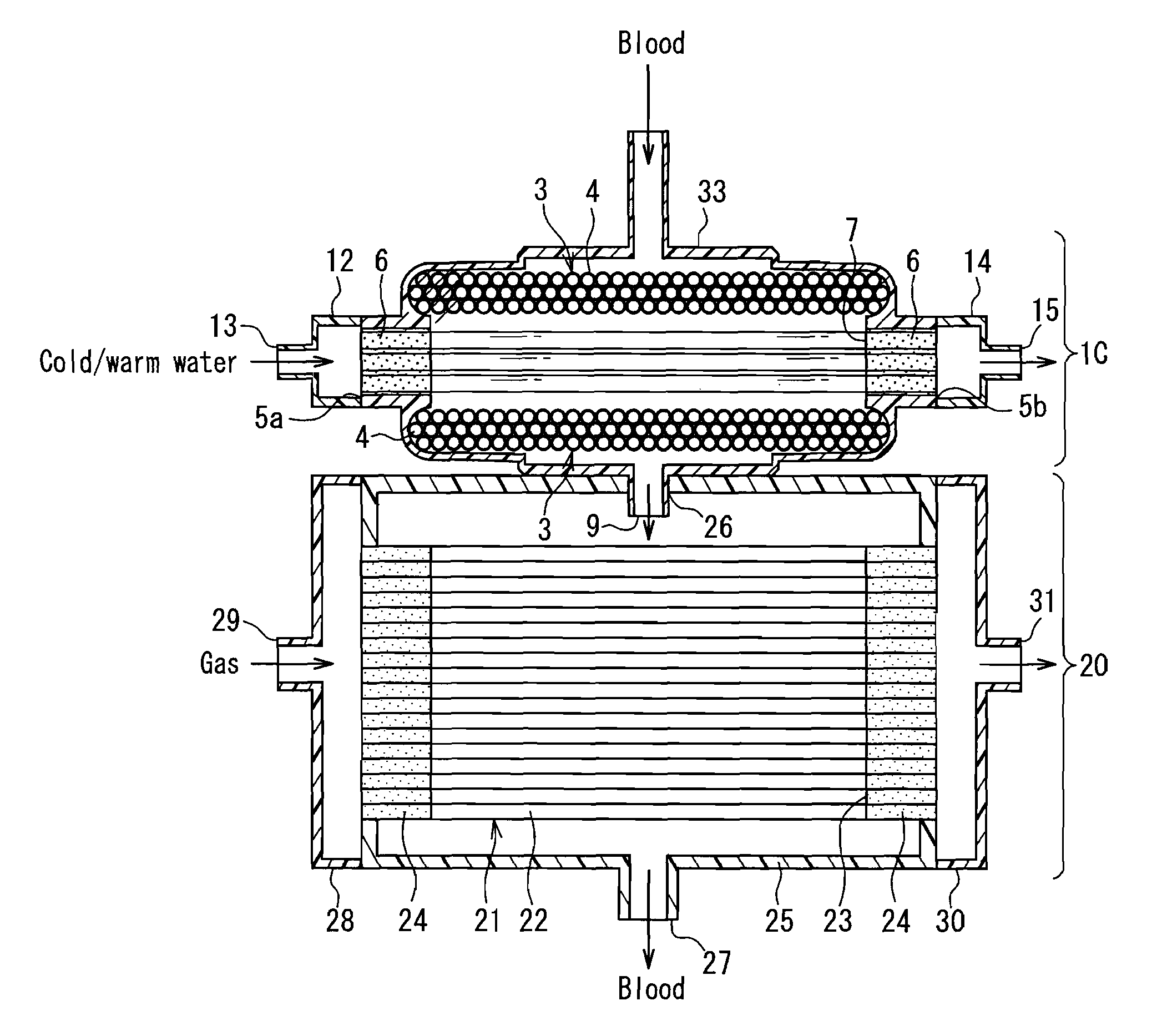
[0117]The configurations of a heat exchanger and an artificial heart-lung machine according to Embodiment 3 of the present invention will be described using FIGS. 9 and 10. FIG. 9 is a perspective view schematically showing the configuration of a heat exchanger 1C of the present embodiment. FIG. 10 is a cross-sectional view schematically showing the configuration of an artificial heart-lung machine including the heat exchanger 1C of the present embodiment. It should be noted that in FIGS. 9 and 10, the same elements as those of the heat exchanger 1A or 1B and the artificial heart-lung machine of Embodiment 1 shown in FIGS. 1 and 2 or Embodiment 2 shown in FIGS. 6 and 7 are given the same reference numerals to simplify the description thereof.

[0118]As shown in FIGS. 9 and 10, in the heat exchanger 1C of the present embodiment, hollow fiber membranes 3 are disposed on both of an entrance side and an exit side of a first blood channel 7 in a housing 33. Moreover, the housing 33 include...


PUM


Abstract

A heat exchanger includes a plurality of tubes 2 through an inner cavity of which a heat-transfer medium liquid flows, a sealing member 6 that seals the plurality of tubes 2 while exposing both ends thereof, with a blood channel passing outside each of the tubes 2 being formed in a central portion in the axial direction of the tubes, and a housing 5 that accommodates the tubes 2 sealed with the sealing member 6. The heat exchanger further includes a hollow fiber membrane 3 that is formed of a plurality of hydrophobic and gas permeable hollow fibers 4 and that is disposed on at least one of an entrance side and an exit side of the blood channel in the housing 5 so that a liquid flowing through the blood channel passes through the hollow fiber membrane 3. The housing 5 includes openings 10 for exposing open ends of each of the hollow fibers 4 forming the hollow fiber membrane 3 to the outside, and gaps between an inner side of the openings and the hollow fibers 4 are sealed. Air can be removed while suppressing a reduction in the heat exchange efficiency.

Description

TECHNICAL FIELD[0001]The present invention relates to a heat exchanger, in particular, a heat exchanger for medical use that is suitable for use in a medical device such as an artificial heart-lung machine, and to an artificial heart-lung machine equipped with the heat exchanger.BACKGROUND ART[0002]In heart surgery and the like, an artificial heart-lung machine is used to take over the respiratory function and the circulatory function of a patient under going the surgery. Moreover, during the surgery, in order to reduce the oxygen consumption by the patient, it is necessary to lower the patient's body temperature and maintain the lowered body temperature. For this purpose, the artificial heart-lung machine is equipped with a heat-exchanging portion and thereby controls the temperature of blood taken from the patient.[0003]Now, the configuration of a conventional example of an artificial heart-lung machine will be described using FIG. 14. FIG. 14 is a cross-sectional view schematical...

Claims


Application Information

Patent Timeline
Patent Type & Authority Patents(United States)
IPC IPC(8): A61M1/00A61M37/00
CPCA61M1/1698B01D53/22B01D63/02A61M1/1625B01D2313/38B01D2325/38B01D2313/221A61M1/3623
Inventor TANAKA, MINORUNIITSUMA, TOMOKAZUKAWARABATA, SHIGEKIMATSUSHITA, TAKASHI
Owner JMS CO LTD
Why Eureka
Try Eureka