
Liquid crystal display and base structure thereof

a liquid crystal and display technology, applied in the field of base structure, can solve the problems of large inconvenience in disassembly and assembly, and achieve the effect of convenient operation

Active Publication Date: 2012-04-03
AMTRAN TECH CO LTD
View PDF9 Cites 4 Cited by
  • Summary
  • Abstract
  • Description
  • Claims
  • Application Information

AI Technical Summary

Benefits of technology

Facilitates easy and tool-free assembly and disassembly of the support and seat, enhancing operational convenience and reducing the risk of losing components.

Problems solved by technology

Meanwhile, the user bears the risk that the locking member is dropped or lost in the disassembly and assembly process, which causes great inconvenience to the disassembly and assembly.

Method used


Image

  • Liquid crystal display and base structure thereof
  • Liquid crystal display and base structure thereof
  • Liquid crystal display and base structure thereof

Examples


Embodiment Construction

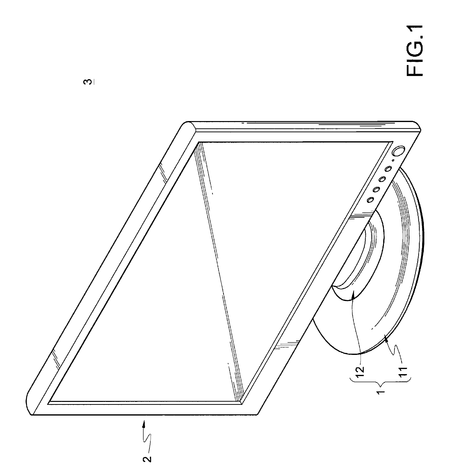
[0024]As shown in FIG. 1, a base structure 1 provided in an embodiment of the present invention is applied to an LCD 3 for supporting a display 2 on a plane (not shown) such as a tabletop or ground surface.

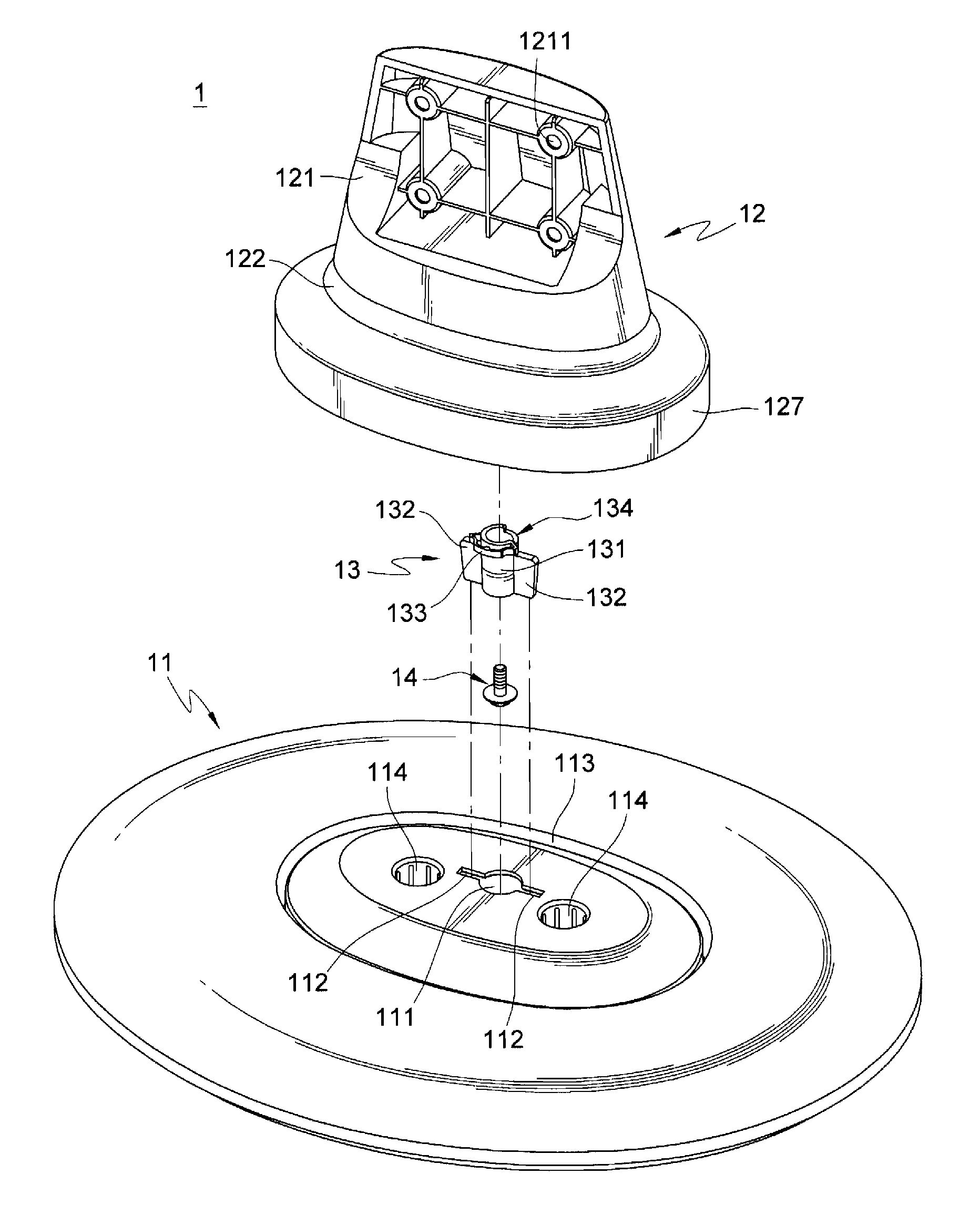
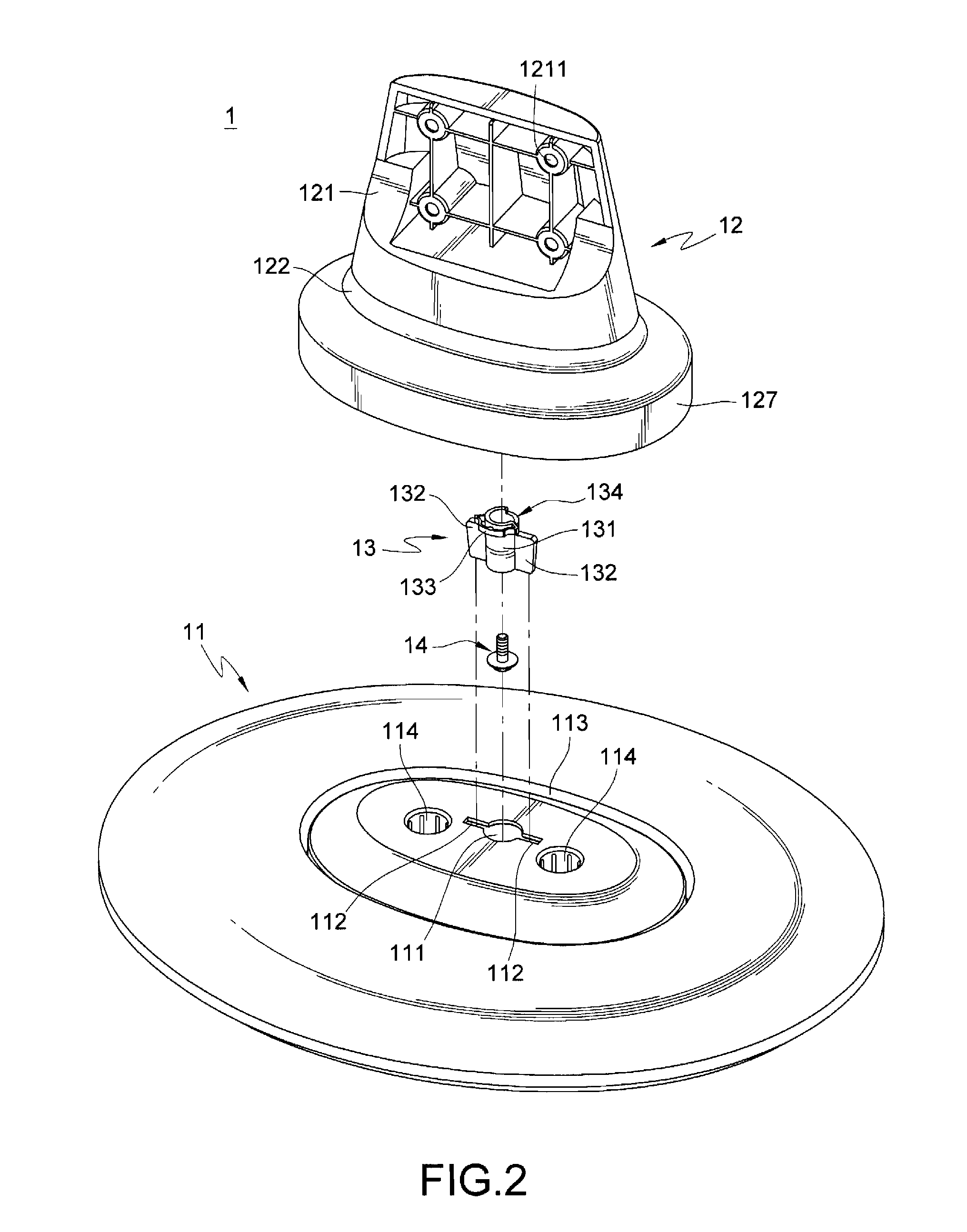
[0025]Referring to FIGS. 1 to 3, the base structure 1 has a seat 11, a support 12, and a limiting member 14. The seat 11 has a locking hole 111, two slots 112, a groove 113, and two positioning holes 114. The locking hole 111 and the slots 112 pass through the seat 11. Two slots 112 extend from a periphery at two opposite sides of the locking hole 111. The groove 113 is annularly disposed at one surface of the seat 11 opposite to the support 12, and the locking hole 111, the slots 112, and the positioning holes 114 are located in a range surrounded by the groove 113. The two positioning holes 114 are respectively disposed at two sides of the locking hole 111. Moreover, the positioning holes 114 may be disposed in a manner of passing through the seat 11 or merely passing through th...


PUM


Abstract

A base structure is used for bearing a display. The base structure includes a support and a seat. The support is connected to a display at one end and detachably disposed on the seat at the other end. The support has a buckling member, and the seat has at least one slot. The buckling member is fitted on the end of the support disposed on the seat, and is rotatable between a release position and a clamping position relative to the support. The buckling member has at least one baffle. When the buckling member is at the release position, the support is detached from the seat by passing the baffle through the slot. When the buckling member is at the clamping position, the baffle and the slot form an angle, and the baffle and the seat have a retaining relationship so as to lock the support on the seat.

Description

BACKGROUND OF THE INVENTION[0001]1. Field of Invention[0002]The present invention relates to a base structure, and more particularly to a base structure for bearing a display.[0003]2. Related Art[0004]Since its appearance, television has provided a user with the opportunity of viewing the newest things over the world at home and getting entertainment and knowledge. With the rapid development of the electronic industry, television has progressed from the earliest cathode ray tube (CRT) to the currently most popular thin display such as liquid crystal display (LCD) and plasma display panel (PDP). Meanwhile, compared with the CRT, the thin display is characterized in having a light weight, thin thickness, and high-quality image display effect, and is thus widely applied in computers or various video devices.[0005]Having a structural form different from that of the early CRT, the thin display cannot directly stand on a plane like a tabletop or ground surface, so that the thin display mu...

Claims


Application Information

Patent Timeline
Patent Type & Authority Patents(United States)
IPC IPC(8): G09G3/36
CPCF16M11/00F16M11/22F16M2200/02F16M2200/08
Inventor WU, YU-CHINGHSU, WEI-CHIEH
Owner AMTRAN TECH CO LTD
Learn More