Self-inflated micro-glass blowing

a technology of micro-glass and blown glass, which is applied in the direction of glass reforming apparatus, turning machine accessories, drawing profiling tools, etc., can solve the problems of only being filled with certain light gases and the fabricated microspheres are not attached to the substrate, and achieve accurate control

Active Publication Date: 2012-04-10
RGT UNIV OF CALIFORNIA
View PDF2 Cites 19 Cited by
  • Summary
  • Abstract
  • Description
  • Claims
  • Application Information

AI Technical Summary

Benefits of technology

[0019]The step of disposing a sheet of thermally formable material comprises bonding the thermally formable material inside a controlled pressure environment so that the volume of the corresponding micro-object formed by the thermally generated pressure can be accurately controlled.
[0024]The step of simultaneously forming a plurality of blown micro-objects in the sheet on the wafer by means of continued application of pressure for a predetermined time comprises controlling the pressure of the surrounding environment so that the volume of the corresponding micro-object formed by the thermally generated pressure can be accurately controlled.

Problems solved by technology

However, previously fabricated microspheres are not attached to a substrate and can only be filled with certain light gases (e.g. hydrogen) through diffusion.

Method used


Image

  • Self-inflated micro-glass blowing
  • Self-inflated micro-glass blowing
  • Self-inflated micro-glass blowing

Examples


Embodiment Construction

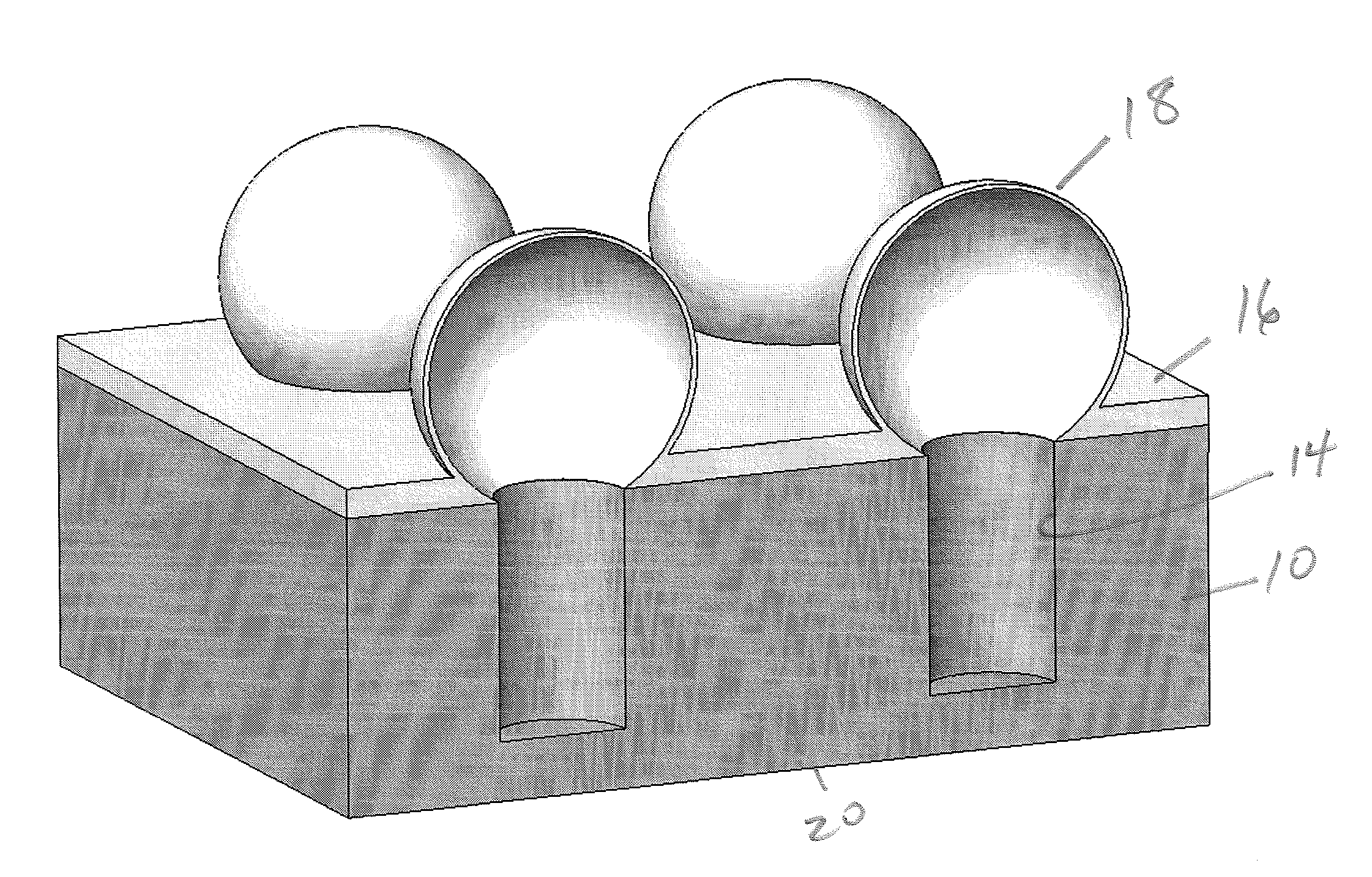
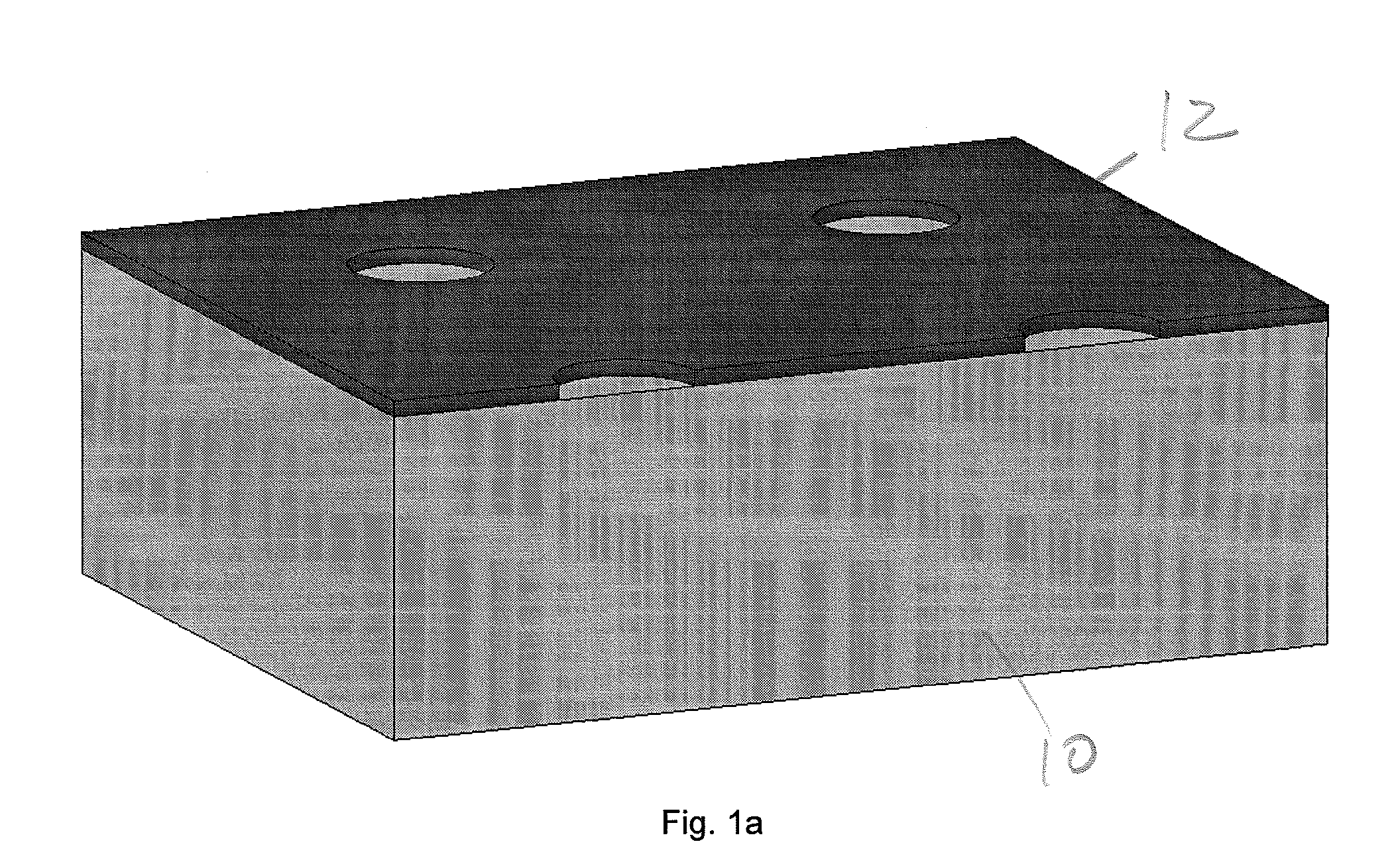
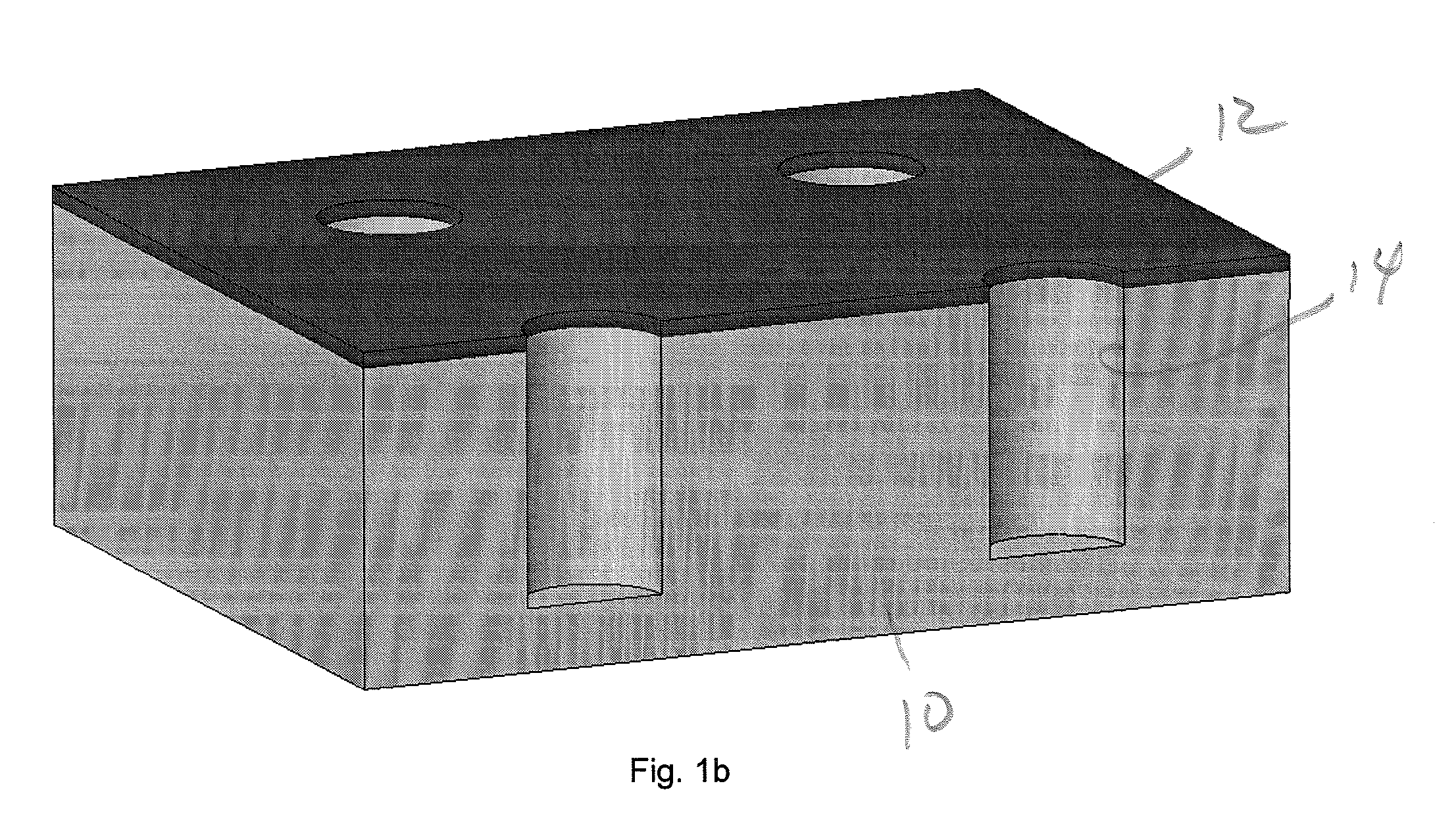
[0044]The illustrated embodiments of the invention disclosed below provide a way of simultaneously forming multiple microscopic glass components on a wafer. These glass-structures are orders of magnitude smaller than what can be achieved using traditional glass blowing techniques. In the illustrated embodiment, the glass spheres are attached to a wafer, allowing for integration with traditional micro-fabrication techniques. Furthermore, the glass structures can be filled with gaseous, liquid, and / or solid materials post fabrication.

[0045]The illustrated embodiment of the invention satisfies the need to implement a microscopic gas confinement chamber. Many specific applications for such a chamber can be considered, e.g. nuclear magnetic resonance gyroscopes, microlamps, and hydrogen capsules for H-vehicles. Other possible applications include micro-lenses, optical switches, laser fusion targets, magnetic shielding when a shielding material is applied on the inside / outside of the sphe...


PUM

PropertyMeasurementUnit
temperatureaaaaaaaaaa
diameteraaaaaaaaaa
diameteraaaaaaaaaa

Abstract

A method for glass-blowing on a microscopic level includes the steps of defining a plurality of microholes in a wafer, disposing a sheet of thermally formable material onto the wafer covering the microholes, heating the sheet of thermally formable material until a predetermined degree of plasticity is achieved, applying self-induced fluidic pressure by expansion of the heated trapped gas in the microholes to the sheet of thermally formable material, while the sheet is still plastic, and simultaneously forming a plurality of blown micro-objects in the sheet on the wafer by means of continued application of pressure for a predetermined time.

Description

RELATED APPLICATIONS[0001]The present application is related to U.S. Provisional Patent Application Ser. No. 60 / 915,904, filed on May 3, 2007, which is incorporated herein by reference and to which priority is claimed pursuant to 35 USC 119.BACKGROUND OF THE INVENTION[0002]1. Field of the Invention[0003]The invention relates to a method for shaping glass on a microscopic scale utilizing self-inflation.[0004]2. Description of the Prior Art[0005]Glass blowing is an art that dates back over 2000 years. Today, glass blowing is used in a wide array of applications, including scientific glassware, optical components, consumer glass containers, and visual arts. Although blow-molding techniques are used in the glass industry to automate the fabrication of bottles and other containers, many fine glass products are still shaped one at a time by glass blowers.[0006]The property that enables the successful shaping of glass is that its viscosity is highly dependent on the temperature. In order t...

Claims


Application Information

Patent Timeline
Patent Type & Authority Patents(United States)
IPC IPC(8): C03B9/31C03B19/10C03B19/08
CPCC03B23/02C03C11/007B82Y40/00G01C19/60B81C1/00119B29C49/0042B29C51/008B29D11/00365B81B2201/0242B81B2201/058B81B2203/0315B01L3/502707Y10T428/24998
Inventor EKLUND, ERIK JESPERSHKEL, ANDREI M
Owner RGT UNIV OF CALIFORNIA
Why Eureka
Try Eureka