Supercharge Your Innovation With Domain-Expert AI Agents!

Roof panel and cab with the same, and method of manufacturing cab

a technology of cab and roof panel, which is applied in the direction of roofs, manufacturing tools, transportation and packaging, etc., can solve the problems of distorted roof panel, and achieve the effect of simple configuration

Active Publication Date: 2012-04-10
KOMATSU LTD
View PDF11 Cites 2 Cited by
  • Summary
  • Abstract
  • Description
  • Claims
  • Application Information

AI Technical Summary

Benefits of technology

The present invention provides a roof panel for a work vehicle cab that prevents denting of the roof panel after assembly. The roof panel includes a planar portion and a plurality of bent portions formed on the outer surface of the planar portion. The bent portions are angled with respect to the planar portion to prevent denting. The roof panel can be easily manufactured without adding additional components and can be held in place by clamps or the like during assembly. The roof panel can be mounted onto the cab roof without welding and can still prevent denting. The roof panel is designed to have a desired shape and can be held in place by clamps or the like.

Problems solved by technology

However, the aforementioned known work vehicle cab roof structure has the following problems.
Even in the case where the roof panel is made of a steel plate, the roof panel may be distorted due to thermal contraction after a welding process in cab assembling procedure.

Method used


Image

  • Roof panel and cab with the same, and method of manufacturing cab
  • Roof panel and cab with the same, and method of manufacturing cab
  • Roof panel and cab with the same, and method of manufacturing cab

Examples


first embodiment

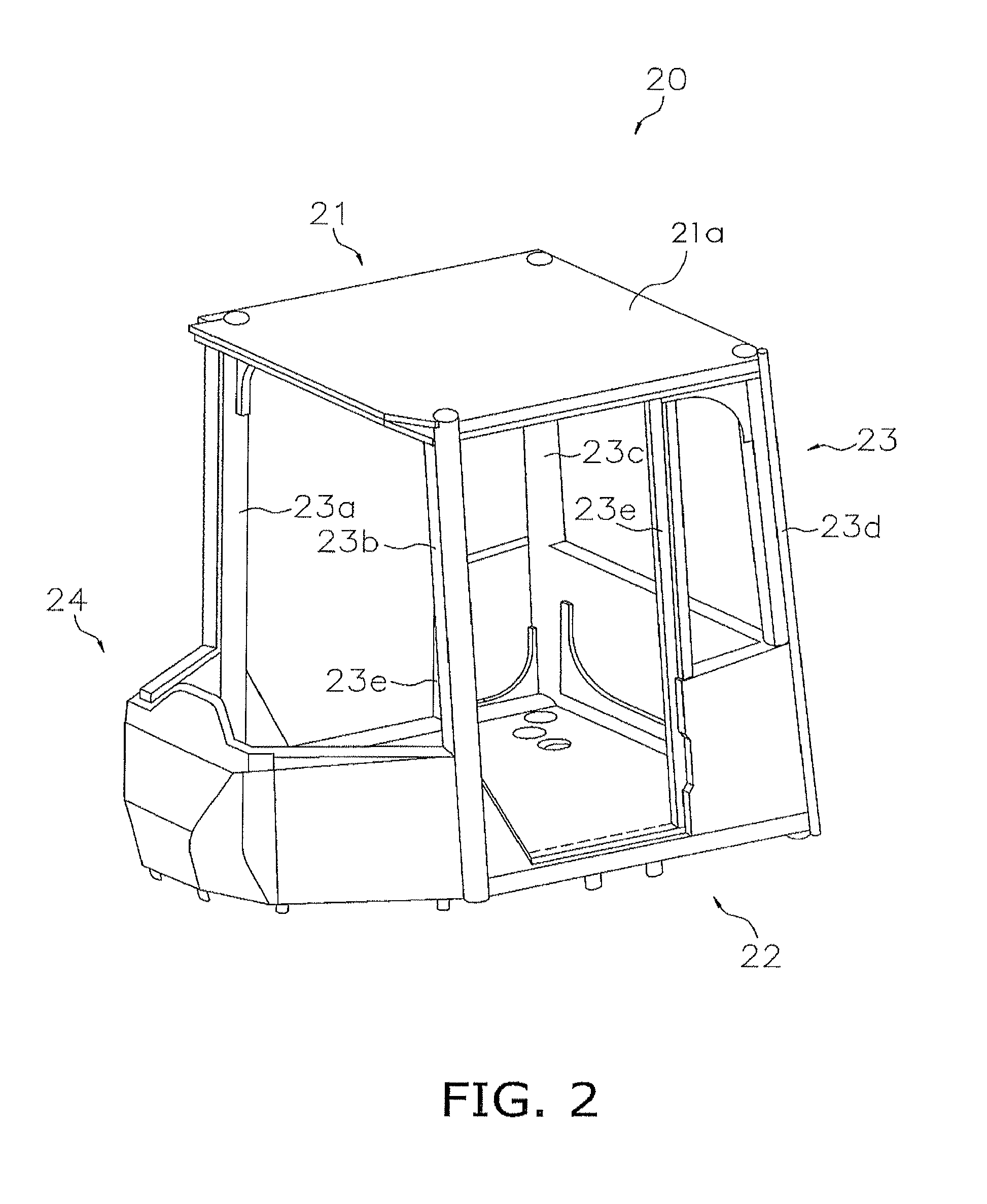
[0056]With reference to FIGS. 1 through 13, the following description will describe a roof panel 21a according to an embodiment of the present invention, a cab 20 that includes a roof surface including the roof panel 21a, and a method of manufacturing the cab 20.

Overall Configuration of Cab 20

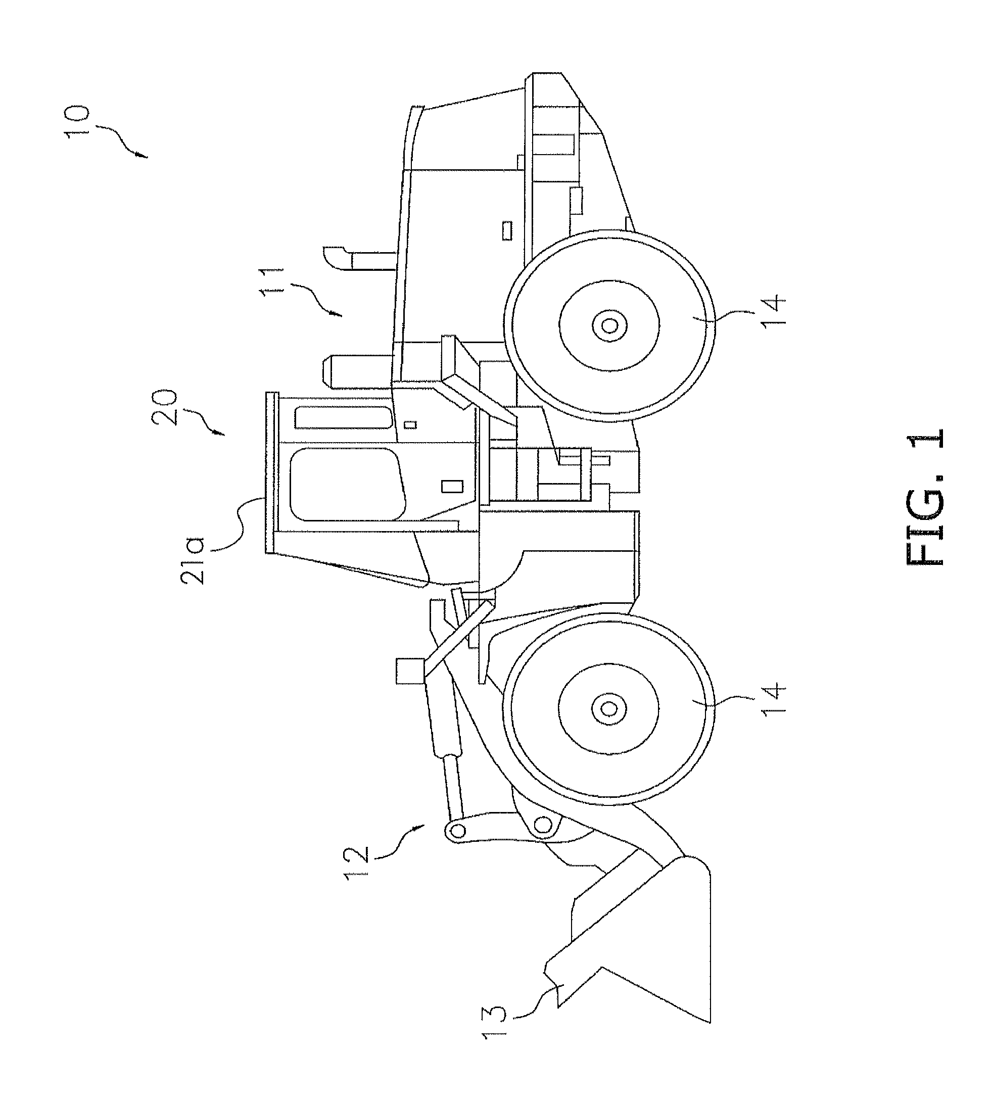
[0057]As shown in FIG. 1, the roof panel 21a according to this embodiment is applied to the cab 20, which is installed on a wheel loader (work vehicle) 10.

[0058]The wheel loader 10 includes a body 11, a lift arm 12, a bucket 13, four tires 14, and the cab 20. The lift arm 12 is mounted to a front part of the body. The bucket 13 is mounted to the fore end of the lift arm 12. The tires 14 bear the body 11, and revolve so that the body runs. The cab 20 is mounted on an upper part of the body 11.

[0059]The body 11 includes an engine compartment and actuator portions. The engine compartment accommodates an engine (not shown). The actuator portions actuate the lift arm 12 and the bucket 13.

[0060]The l...

second embodiment

[0111]With reference to FIGS. 14 through 18, the following description will describe a roof panel 71a according to another embodiment of the present invention, a cab 120 that includes a roof surface including the roof panel 71a, and a method of manufacturing the cab 120.

[0112]As shown in FIG. 14, the cab 120 according to this embodiment is installed on a bulldozer 110 that includes a body 111, lift arms 112, a dozing blade 113, and crawler belts 114.

[0113]As shown in FIGS. 15(a) to 15(c), the roof panel 71a with a generally hexagonal shape is used as a member that composes a roof surface of the cab 120. The generally hexagonal shape has a narrow edge of the roof panel 71a on the vehicle front side in plan view.

Configuration of Roof Panel 71a

[0114]Before secured to the roof part of the cab 120 by welding, as shown in FIGS. 15(a) to 15(c), the roof panel 71a is formed of a metal plate-shaped component that includes a rectangular planar portion 91 and bent portions 92a to 92d. The ben...


PUM

PropertyMeasurementUnit
angleaaaaaaaaaa
bending angleaaaaaaaaaa
angleaaaaaaaaaa

Abstract

A roof panel of a cab installed on a work vehicle includes a planar portion and a plurality of bent portions. The planar portion serves as the roof surface of the work vehicle cab. The bent portions are formed on the outer periphery of the planar portion. The bent portions are bent at a predetermined angle with respect to the planar portion toward an external side of the roof surface of the work vehicle cab.

Description

CROSS-REFERENCE TO RELATED APPLICATIONS[0001]This national phase application claims priority to Japanese Patent Application No. 2007-108654, filed on Apr. 17, 2007. The entire disclosure of Japanese Patent Application No. 2007-108654 is hereby incorporated herein by reference.TECHNICAL FIELD[0002]The present invention relates to a roof panel that composes a roof surface of work vehicles such as bulldozer, hydraulic excavator, wheel loader and dumper truck, and a cab including the roof panel and a method of manufacturing the cab.BACKGROUND ART[0003]Conventional work vehicles such as wheel loader, bulldozer and hydraulic excavator include a cab (operator compartment) as an operator's room that is composed of square steel pipes or deformed steel pipes, panels and the like that are coupled to each other.[0004]For example, Japanese Patent Laid-Open Publication No. 2002-249073 (published on Sep. 3, 2002) discloses a roof structure of a work vehicle cab that, in order to prevent that an ou...

Claims


Application Information

Patent Timeline
Patent Type & Authority Patents(United States)
IPC IPC(8): B62D25/06
CPCB23K31/02E02F9/163B62D33/0617B23K2201/006Y10T29/49826B23K2101/006
Inventor KAMIMAE, TAKESHIYOMOGITA, MAKOTO
Owner KOMATSU LTD
Features
  • R&D
  • Intellectual Property
  • Life Sciences
  • Materials
  • Tech Scout
  • Unparalleled Data Quality
  • Higher Quality Content
  • 60% Fewer Hallucinations
Learn More