
Enhanced efficiency low-dropout linear regulator and corresponding method

a linear regulator and high-efficiency technology, applied in the direction of electric variable regulation, process and machine control, instruments, etc., can solve the problems of low efficiency at medium loads, and almost unaffected ldo stability, so as to achieve high-efficiency low-dropout and improve efficiency

Active Publication Date: 2012-04-10
MICROELECTRONIC INNOVATIONS LLC
View PDF9 Cites 3 Cited by
  • Summary
  • Abstract
  • Description
  • Claims
  • Application Information

AI Technical Summary

Benefits of technology

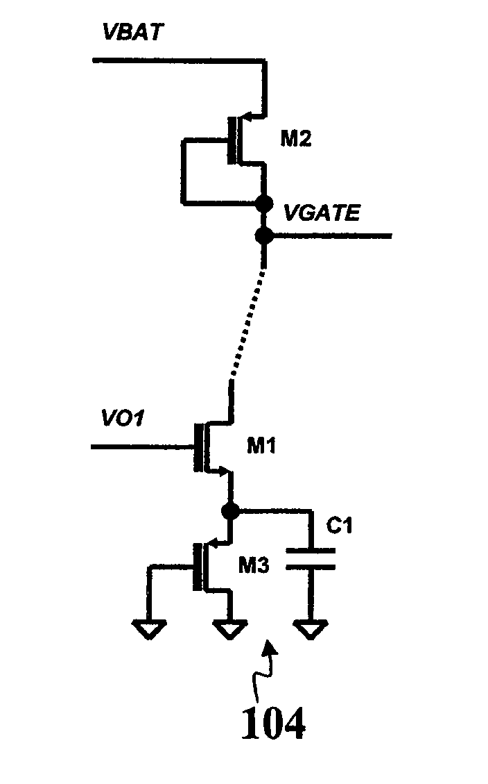
"The invention provides a new and efficient low-dropout regulator (LDO) that consumes current linearly proportional to the load current, while maintaining stability. The LDO includes an error amplifier with a cascaded arrangement of a differential amplifier and a gain stage. The gain stage includes a transistor driven by the differential amplifier to produce the drive signal for the output stage of the regulator. The transistor is interposed over its source-drain line between a first resistive load and a second resistive load to achieve the desired linear current consumption. The first resistive load is a non-linear element causing the frequency of the zero created by the RC network to decrease as the load current of the regulator decreases. This new LDO arrangement offers improved efficiency and stability while being easy to implement."

Problems solved by technology

As a result, current consumption is not linearly proportional to the output current of LDO.
This consumption profile causes lower efficiency at medium loads; however, the LDO stability is almost unaffected by any variations in the load current.
The phase margin at middle frequencies is thus decreased and stability of the LDO is now adversely affected by load current variation.

Method used


Image

  • Enhanced efficiency low-dropout linear regulator and corresponding method
  • Enhanced efficiency low-dropout linear regulator and corresponding method
  • Enhanced efficiency low-dropout linear regulator and corresponding method

Examples


Embodiment Construction

[0024]In the following description, numerous specific details are given to provide a thorough understanding of embodiments. The embodiments can be practiced without one or more of the specific details, or with other methods, components, materials, etc. In other instances, well-known structures, materials, or operations are not shown or described in detail to avoid obscuring aspects of the embodiments.

[0025]Reference throughout this specification to “one embodiment” or “an embodiment” means that a particular feature, structure, or characteristic described in connection with the embodiment is included in at least one embodiment. Thus, the appearances of the phrases “in one embodiment” or “in an embodiment” in various places throughout this specification are not necessarily all referring to the same embodiment. Furthermore, the particular features, structures, or characteristics may be combined in any suitable manner in one or more embodiments.

[0026]The headings provided herein are for...


PUM


Abstract

A low-dropout linear regulator includes an error amplifier which includes a cascaded arrangement of a differential amplifier and a gain stage. The gain stage includes a transistor driven by the differential amplifier to produce at a drive signal for an output stage of the regulator. The transistor is interposed over its source-drain line between a first resistive load included in a RC network creating a zero in the open loop gain of the regulator, and a second resistive load to produce a drive signal for the output stage of the regulator. The second resistive load is a non-linear compensation element to render current consumption linearly proportional to the load current to the regulator. The first resistive load is a non-linear element causing the frequency of said zero created by the RC network to decrease as the load current of the regulator decreases.

Description

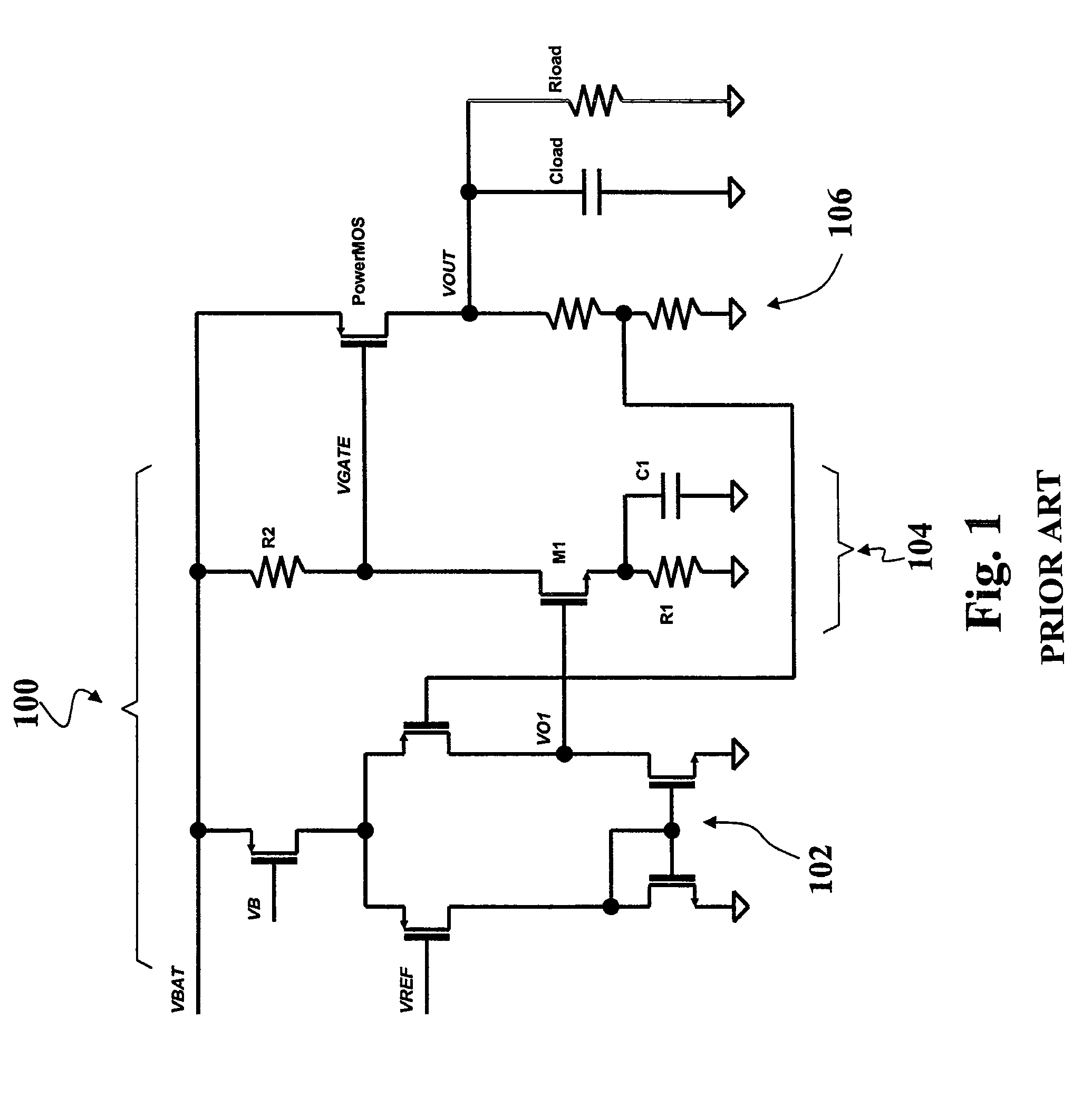
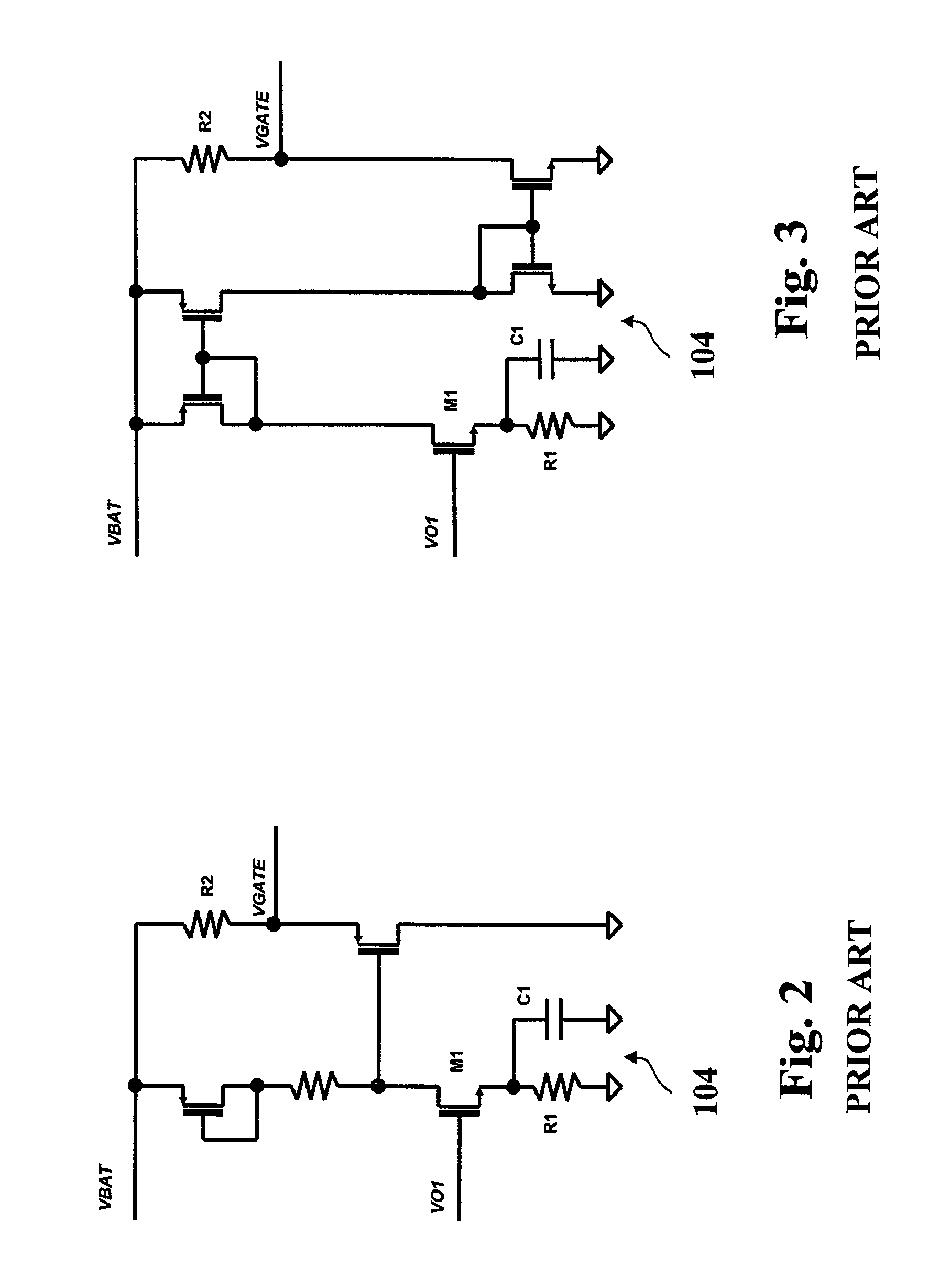
RELATED APPLICATION[0001]This application claims priority of Italian Patent Application No. TO2008A000933 filed Dec. 15, 2008, which is incorporated herein in its entirety by this reference.FIELD OF THE INVENTION[0002]This disclosure relates to low-dropout linear regulators (LDOs). LDOs are used in a wide variety of applications in electronics to apply to a load a signal regulated as a function of a reference signal.DESCRIPTION OF THE RELATED ART[0003]The diagram of FIG. 1 is exemplary of the circuit layout of a conventional low-dropout linear regulator. The LDO of FIG. 1 is essentially comprised of a cascaded arrangement of an error amplifier 100 (in turn including a differential amplifier 102 receiving the reference signal VREF followed by a gain stage 104) and an output stage 106. The output stage 106 includes a Power MOS which receives from the gain stage 104 a voltage VGATE at its gate and applies an output voltage VOUT to a load including a resistive component Rload and a capa...

Claims


Application Information

Patent Timeline
Patent Type & Authority Patents(United States)
IPC IPC(8): G05F1/40
CPCG05F1/575
Inventor NAPRAVNIK, KAREL
Owner MICROELECTRONIC INNOVATIONS LLC
Learn More